

sylvain carva
-
Compteur de contenus
4 -
Inscrit(e) le
-
Dernière visite
Tout ce qui a été posté par sylvain carva
-
bonjour jais fait la mise a jour de mon firmware sur une imprimante DIY , matériel carte arduino ( model non marquer je dirais une mega 2560 a la taille) board : GPL3 de bigtreetech contrôleur : A4988 LCD : RepRapDiscount Full Graphic Smart Controller 2 moteur pour l'axe z brancher a la carte / hotend/rien /bed voila : fichier configuration: /** * Marlin 3D Printer Firmware * Copyright (C) 2016 MarlinFirmware [https://github.com/MarlinFirmware/Marlin] * * Based on Sprinter and grbl. * Copyright (C) 2011 Camiel Gubbels / Erik van der Zalm * * This program is free software: you can redistribute it and/or modify * it under the terms of the GNU General Public License as published by * the Free Software Foundation, either version 3 of the License, or * (at your option) any later version. * * This program is distributed in the hope that it will be useful, * but WITHOUT ANY WARRANTY; without even the implied warranty of * MERCHANTABILITY or FITNESS FOR A PARTICULAR PURPOSE. See the * GNU General Public License for more details. * * You should have received a copy of the GNU General Public License * along with this program. If not, see <http://www.gnu.org/licenses/>. * */ /** * Configuration.h * * Basic settings such as: * * - Type of electronics * - Type of temperature sensor * - Printer geometry * - Endstop configuration * - LCD controller * - Extra features * * Advanced settings can be found in Configuration_adv.h * */ #ifndef CONFIGURATION_H #define CONFIGURATION_H #define CONFIGURATION_H_VERSION 010109 //=========================================================================== //============================= Getting Started ============================= //=========================================================================== /** * Here are some standard links for getting your machine calibrated: * * http://reprap.org/wiki/Calibration * http://youtu.be/wAL9d7FgInk * http://calculator.josefprusa.cz * http://reprap.org/wiki/Triffid_Hunter%27s_Calibration_Guide * http://www.thingiverse.com/thing:5573 * https://sites.google.com/site/repraplogphase/calibration-of-your-reprap * http://www.thingiverse.com/thing:298812 */ //=========================================================================== //============================= DELTA Printer =============================== //=========================================================================== // For a Delta printer start with one of the configuration files in the // example_configurations/delta directory and customize for your machine. // //=========================================================================== //============================= SCARA Printer =============================== //=========================================================================== // For a SCARA printer start with the configuration files in // example_configurations/SCARA and customize for your machine. // //=========================================================================== //============================= HANGPRINTER ================================= //=========================================================================== // For a Hangprinter start with the configuration file in the // example_configurations/hangprinter directory and customize for your machine. // // @section info // User-specified version info of this build to display in [Pronterface, etc] terminal window during // startup. Implementation of an idea by Prof Braino to inform user that any changes made to this // build by the user have been successfully uploaded into firmware. #define STRING_CONFIG_H_AUTHOR "(none, default config)" // Who made the changes. #define SHOW_BOOTSCREEN #define STRING_SPLASH_LINE1 SHORT_BUILD_VERSION // will be shown during bootup in line 1 #define STRING_SPLASH_LINE2 WEBSITE_URL // will be shown during bootup in line 2 /** * *** VENDORS PLEASE READ *** * * Marlin allows you to add a custom boot image for Graphical LCDs. * With this option Marlin will first show your custom screen followed * by the standard Marlin logo with version number and web URL. * * We encourage you to take advantage of this new feature and we also * respectfully request that you retain the unmodified Marlin boot screen. */ // Enable to show the bitmap in Marlin/_Bootscreen.h on startup. //#define SHOW_CUSTOM_BOOTSCREEN // Enable to show the bitmap in Marlin/_Statusscreen.h on the status screen. //#define CUSTOM_STATUS_SCREEN_IMAGE // @section machine /** * Select the serial port on the board to use for communication with the host. * This allows the connection of wireless adapters (for instance) to non-default port pins. * Serial port 0 is always used by the Arduino bootloader regardless of this setting. * * :[0, 1, 2, 3, 4, 5, 6, 7] */ #define SERIAL_PORT 0 /** * This setting determines the communication speed of the printer. * * 250000 works in most cases, but you might try a lower speed if * you commonly experience drop-outs during host printing. * You may try up to 1000000 to speed up SD file transfer. * * :[2400, 9600, 19200, 38400, 57600, 115200, 250000, 500000, 1000000] */ #define BAUDRATE 250000 // Enable the Bluetooth serial interface on AT90USB devices //#define BLUETOOTH // The following define selects which electronics board you have. // Please choose the name from boards.h that matches your setup #ifndef MOTHERBOARD #define MOTHERBOARD BOARD_RAMPS_14_EFB #endif // Optional custom name for your RepStrap or other custom machine // Displayed in the LCD "Ready" message //#define CUSTOM_MACHINE_NAME "3D Printer" // Define this to set a unique identifier for this printer, (Used by some programs to differentiate between machines) // You can use an online service to generate a random UUID. (eg http://www.uuidgenerator.net/version4) //#define MACHINE_UUID "00000000-0000-0000-0000-000000000000" // @section extruder // This defines the number of extruders // :[1, 2, 3, 4, 5] #define EXTRUDERS 1 // Generally expected filament diameter (1.75, 2.85, 3.0, ...). Used for Volumetric, Filament Width Sensor, etc. #define DEFAULT_NOMINAL_FILAMENT_DIA 3.0 // For Cyclops or any "multi-extruder" that shares a single nozzle. //#define SINGLENOZZLE /** * Průša MK2 Single Nozzle Multi-Material Multiplexer, and variants. * * This device allows one stepper driver on a control board to drive * two to eight stepper motors, one at a time, in a manner suitable * for extruders. * * This option only allows the multiplexer to switch on tool-change. * Additional options to configure custom E moves are pending. */ //#define MK2_MULTIPLEXER #if ENABLED(MK2_MULTIPLEXER) // Override the default DIO selector pins here, if needed. // Some pins files may provide defaults for these pins. //#define E_MUX0_PIN 40 // Always Required //#define E_MUX1_PIN 42 // Needed for 3 to 8 steppers //#define E_MUX2_PIN 44 // Needed for 5 to 8 steppers #endif // A dual extruder that uses a single stepper motor //#define SWITCHING_EXTRUDER #if ENABLED(SWITCHING_EXTRUDER) #define SWITCHING_EXTRUDER_SERVO_NR 0 #define SWITCHING_EXTRUDER_SERVO_ANGLES { 0, 90 } // Angles for E0, E1[, E2, E3] #if EXTRUDERS > 3 #define SWITCHING_EXTRUDER_E23_SERVO_NR 1 #endif #endif // A dual-nozzle that uses a servomotor to raise/lower one of the nozzles //#define SWITCHING_NOZZLE #if ENABLED(SWITCHING_NOZZLE) #define SWITCHING_NOZZLE_SERVO_NR 0 #define SWITCHING_NOZZLE_SERVO_ANGLES { 0, 90 } // Angles for E0, E1 //#define HOTEND_OFFSET_Z { 0.0, 0.0 } #endif /** * Two separate X-carriages with extruders that connect to a moving part * via a magnetic docking mechanism. Requires SOL1_PIN and SOL2_PIN. */ //#define PARKING_EXTRUDER #if ENABLED(PARKING_EXTRUDER) #define PARKING_EXTRUDER_SOLENOIDS_INVERT // If enabled, the solenoid is NOT magnetized with applied voltage #define PARKING_EXTRUDER_SOLENOIDS_PINS_ACTIVE LOW // LOW or HIGH pin signal energizes the coil #define PARKING_EXTRUDER_SOLENOIDS_DELAY 250 // Delay (ms) for magnetic field. No delay if 0 or not defined. #define PARKING_EXTRUDER_PARKING_X { -78, 184 } // X positions for parking the extruders #define PARKING_EXTRUDER_GRAB_DISTANCE 1 // mm to move beyond the parking point to grab the extruder #define PARKING_EXTRUDER_SECURITY_RAISE 5 // Z-raise before parking #define HOTEND_OFFSET_Z { 0.0, 1.3 } // Z-offsets of the two hotends. The first must be 0. #endif /** * "Mixing Extruder" * - Adds G-codes M163 and M164 to set and "commit" the current mix factors. * - Extends the stepping routines to move multiple steppers in proportion to the mix. * - Optional support for Repetier Firmware's 'M164 S<index>' supporting virtual tools. * - This implementation supports up to two mixing extruders. * - Enable DIRECT_MIXING_IN_G1 for M165 and mixing in G1 (from Pia Taubert's reference implementation). */ //#define MIXING_EXTRUDER #if ENABLED(MIXING_EXTRUDER) #define MIXING_STEPPERS 2 // Number of steppers in your mixing extruder #define MIXING_VIRTUAL_TOOLS 16 // Use the Virtual Tool method with M163 and M164 //#define DIRECT_MIXING_IN_G1 // Allow ABCDHI mix factors in G1 movement commands #endif // Offset of the extruders (uncomment if using more than one and relying on firmware to position when changing). // The offset has to be X=0, Y=0 for the extruder 0 hotend (default extruder). // For the other hotends it is their distance from the extruder 0 hotend. //#define HOTEND_OFFSET_X {0.0, 20.00} // (in mm) for each extruder, offset of the hotend on the X axis //#define HOTEND_OFFSET_Y {0.0, 5.00} // (in mm) for each extruder, offset of the hotend on the Y axis // @section machine /** * Select your power supply here. Use 0 if you haven't connected the PS_ON_PIN * * 0 = No Power Switch * 1 = ATX * 2 = X-Box 360 203Watts (the blue wire connected to PS_ON and the red wire to VCC) * * :{ 0:'No power switch', 1:'ATX', 2:'X-Box 360' } */ #define POWER_SUPPLY 0 #if POWER_SUPPLY > 0 // Enable this option to leave the PSU off at startup. // Power to steppers and heaters will need to be turned on with M80. //#define PS_DEFAULT_OFF //#define AUTO_POWER_CONTROL // Enable automatic control of the PS_ON pin #if ENABLED(AUTO_POWER_CONTROL) #define AUTO_POWER_FANS // Turn on PSU if fans need power #define AUTO_POWER_E_FANS #define AUTO_POWER_CONTROLLERFAN #define POWER_TIMEOUT 30 #endif #endif // @section temperature //=========================================================================== //============================= Thermal Settings ============================ //=========================================================================== /** * --NORMAL IS 4.7kohm PULLUP!-- 1kohm pullup can be used on hotend sensor, using correct resistor and table * * Temperature sensors available: * * -4 : thermocouple with AD8495 * -3 : thermocouple with MAX31855 (only for sensor 0) * -2 : thermocouple with MAX6675 (only for sensor 0) * -1 : thermocouple with AD595 * 0 : not used * 1 : 100k thermistor - best choice for EPCOS 100k (4.7k pullup) * 2 : 200k thermistor - ATC Semitec 204GT-2 (4.7k pullup) * 3 : Mendel-parts thermistor (4.7k pullup) * 4 : 10k thermistor !! do not use it for a hotend. It gives bad resolution at high temp. !! * 5 : 100K thermistor - ATC Semitec 104GT-2/104NT-4-R025H42G (Used in ParCan & J-Head) (4.7k pullup) * 501 : 100K Zonestar (Tronxy X3A) Thermistor * 6 : 100k EPCOS - Not as accurate as table 1 (created using a fluke thermocouple) (4.7k pullup) * 7 : 100k Honeywell thermistor 135-104LAG-J01 (4.7k pullup) * 71 : 100k Honeywell thermistor 135-104LAF-J01 (4.7k pullup) * 8 : 100k 0603 SMD Vishay NTCS0603E3104FXT (4.7k pullup) * 9 : 100k GE Sensing AL03006-58.2K-97-G1 (4.7k pullup) * 10 : 100k RS thermistor 198-961 (4.7k pullup) * 11 : 100k beta 3950 1% thermistor (4.7k pullup) * 12 : 100k 0603 SMD Vishay NTCS0603E3104FXT (4.7k pullup) (calibrated for Makibox hot bed) * 13 : 100k Hisens 3950 1% up to 300°C for hotend "Simple ONE " & "Hotend "All In ONE" * 15 : 100k thermistor calibration for JGAurora A5 hotend * 20 : the PT100 circuit found in the Ultimainboard V2.x * 60 : 100k Maker's Tool Works Kapton Bed Thermistor beta=3950 * 66 : 4.7M High Temperature thermistor from Dyze Design * 70 : the 100K thermistor found in the bq Hephestos 2 * 75 : 100k Generic Silicon Heat Pad with NTC 100K MGB18-104F39050L32 thermistor * * 1k ohm pullup tables - This is atypical, and requires changing out the 4.7k pullup for 1k. * (but gives greater accuracy and more stable PID) * 51 : 100k thermistor - EPCOS (1k pullup) * 52 : 200k thermistor - ATC Semitec 204GT-2 (1k pullup) * 55 : 100k thermistor - ATC Semitec 104GT-2 (Used in ParCan & J-Head) (1k pullup) * * 1047 : Pt1000 with 4k7 pullup * 1010 : Pt1000 with 1k pullup (non standard) * 147 : Pt100 with 4k7 pullup * 110 : Pt100 with 1k pullup (non standard) * * Use these for Testing or Development purposes. NEVER for production machine. * 998 : Dummy Table that ALWAYS reads 25°C or the temperature defined below. * 999 : Dummy Table that ALWAYS reads 100°C or the temperature defined below. * * :{ '0': "Not used", '1':"100k / 4.7k - EPCOS", '2':"200k / 4.7k - ATC Semitec 204GT-2", '3':"Mendel-parts / 4.7k", '4':"10k !! do not use for a hotend. Bad resolution at high temp. !!", '5':"100K / 4.7k - ATC Semitec 104GT-2 (Used in ParCan & J-Head)", '501':"100K Zonestar (Tronxy X3A)", '6':"100k / 4.7k EPCOS - Not as accurate as Table 1", '7':"100k / 4.7k Honeywell 135-104LAG-J01", '8':"100k / 4.7k 0603 SMD Vishay NTCS0603E3104FXT", '9':"100k / 4.7k GE Sensing AL03006-58.2K-97-G1", '10':"100k / 4.7k RS 198-961", '11':"100k / 4.7k beta 3950 1%", '12':"100k / 4.7k 0603 SMD Vishay NTCS0603E3104FXT (calibrated for Makibox hot bed)", '13':"100k Hisens 3950 1% up to 300°C for hotend 'Simple ONE ' & hotend 'All In ONE'", '20':"PT100 (Ultimainboard V2.x)", '51':"100k / 1k - EPCOS", '52':"200k / 1k - ATC Semitec 204GT-2", '55':"100k / 1k - ATC Semitec 104GT-2 (Used in ParCan & J-Head)", '60':"100k Maker's Tool Works Kapton Bed Thermistor beta=3950", '66':"Dyze Design 4.7M High Temperature thermistor", '70':"the 100K thermistor found in the bq Hephestos 2", '71':"100k / 4.7k Honeywell 135-104LAF-J01", '147':"Pt100 / 4.7k", '1047':"Pt1000 / 4.7k", '110':"Pt100 / 1k (non-standard)", '1010':"Pt1000 / 1k (non standard)", '-4':"Thermocouple + AD8495", '-3':"Thermocouple + MAX31855 (only for sensor 0)", '-2':"Thermocouple + MAX6675 (only for sensor 0)", '-1':"Thermocouple + AD595",'998':"Dummy 1", '999':"Dummy 2" } */ #define TEMP_SENSOR_0 1 #define TEMP_SENSOR_1 0 #define TEMP_SENSOR_2 0 #define TEMP_SENSOR_3 0 #define TEMP_SENSOR_4 0 #define TEMP_SENSOR_BED 0 #define TEMP_SENSOR_CHAMBER 0 // Dummy thermistor constant temperature readings, for use with 998 and 999 #define DUMMY_THERMISTOR_998_VALUE 25 #define DUMMY_THERMISTOR_999_VALUE 100 // Use temp sensor 1 as a redundant sensor with sensor 0. If the readings // from the two sensors differ too much the print will be aborted. //#define TEMP_SENSOR_1_AS_REDUNDANT #define MAX_REDUNDANT_TEMP_SENSOR_DIFF 10 // Extruder temperature must be close to target for this long before M109 returns success #define TEMP_RESIDENCY_TIME 10 // (seconds) #define TEMP_HYSTERESIS 3 // (degC) range of +/- temperatures considered "close" to the target one #define TEMP_WINDOW 1 // (degC) Window around target to start the residency timer x degC early. // Bed temperature must be close to target for this long before M190 returns success #define TEMP_BED_RESIDENCY_TIME 10 // (seconds) #define TEMP_BED_HYSTERESIS 3 // (degC) range of +/- temperatures considered "close" to the target one #define TEMP_BED_WINDOW 1 // (degC) Window around target to start the residency timer x degC early. // The minimal temperature defines the temperature below which the heater will not be enabled It is used // to check that the wiring to the thermistor is not broken. // Otherwise this would lead to the heater being powered on all the time. #define HEATER_0_MINTEMP 5 #define HEATER_1_MINTEMP 5 #define HEATER_2_MINTEMP 5 #define HEATER_3_MINTEMP 5 #define HEATER_4_MINTEMP 5 #define BED_MINTEMP 5 // When temperature exceeds max temp, your heater will be switched off. // This feature exists to protect your hotend from overheating accidentally, but *NOT* from thermistor short/failure! // You should use MINTEMP for thermistor short/failure protection. #define HEATER_0_MAXTEMP 275 #define HEATER_1_MAXTEMP 275 #define HEATER_2_MAXTEMP 275 #define HEATER_3_MAXTEMP 275 #define HEATER_4_MAXTEMP 275 #define BED_MAXTEMP 150 //=========================================================================== //============================= PID Settings ================================ //=========================================================================== // PID Tuning Guide here: http://reprap.org/wiki/PID_Tuning // Comment the following line to disable PID and enable bang-bang. #define PIDTEMP #define BANG_MAX 255 // Limits current to nozzle while in bang-bang mode; 255=full current #define PID_MAX BANG_MAX // Limits current to nozzle while PID is active (see PID_FUNCTIONAL_RANGE below); 255=full current #define PID_K1 0.95 // Smoothing factor within any PID loop #if ENABLED(PIDTEMP) //#define PID_AUTOTUNE_MENU // Add PID Autotune to the LCD "Temperature" menu to run M303 and apply the result. //#define PID_DEBUG // Sends debug data to the serial port. //#define PID_OPENLOOP 1 // Puts PID in open loop. M104/M140 sets the output power from 0 to PID_MAX //#define SLOW_PWM_HEATERS // PWM with very low frequency (roughly 0.125Hz=8s) and minimum state time of approximately 1s useful for heaters driven by a relay //#define PID_PARAMS_PER_HOTEND // Uses separate PID parameters for each extruder (useful for mismatched extruders) // Set/get with gcode: M301 E[extruder number, 0-2] #define PID_FUNCTIONAL_RANGE 10 // If the temperature difference between the target temperature and the actual temperature // is more than PID_FUNCTIONAL_RANGE then the PID will be shut off and the heater will be set to min/max. // If you are using a pre-configured hotend then you can use one of the value sets by uncommenting it // Ultimaker #define DEFAULT_Kp 22.2 #define DEFAULT_Ki 1.08 #define DEFAULT_Kd 114 // MakerGear //#define DEFAULT_Kp 7.0 //#define DEFAULT_Ki 0.1 //#define DEFAULT_Kd 12 // Mendel Parts V9 on 12V //#define DEFAULT_Kp 63.0 //#define DEFAULT_Ki 2.25 //#define DEFAULT_Kd 440 #endif // PIDTEMP //=========================================================================== //============================= PID > Bed Temperature Control =============== //=========================================================================== /** * PID Bed Heating * * If this option is enabled set PID constants below. * If this option is disabled, bang-bang will be used and BED_LIMIT_SWITCHING will enable hysteresis. * * The PID frequency will be the same as the extruder PWM. * If PID_dT is the default, and correct for the hardware/configuration, that means 7.689Hz, * which is fine for driving a square wave into a resistive load and does not significantly * impact FET heating. This also works fine on a Fotek SSR-10DA Solid State Relay into a 250W * heater. If your configuration is significantly different than this and you don't understand * the issues involved, don't use bed PID until someone else verifies that your hardware works. */ //#define PIDTEMPBED //#define BED_LIMIT_SWITCHING /** * Max Bed Power * Applies to all forms of bed control (PID, bang-bang, and bang-bang with hysteresis). * When set to any value below 255, enables a form of PWM to the bed that acts like a divider * so don't use it unless you are OK with PWM on your bed. (See the comment on enabling PIDTEMPBED) */ #define MAX_BED_POWER 255 // limits duty cycle to bed; 255=full current #if ENABLED(PIDTEMPBED) //#define PID_BED_DEBUG // Sends debug data to the serial port. //120V 250W silicone heater into 4mm borosilicate (MendelMax 1.5+) //from FOPDT model - kp=.39 Tp=405 Tdead=66, Tc set to 79.2, aggressive factor of .15 (vs .1, 1, 10) #define DEFAULT_bedKp 10.00 #define DEFAULT_bedKi .023 #define DEFAULT_bedKd 305.4 //120V 250W silicone heater into 4mm borosilicate (MendelMax 1.5+) //from pidautotune //#define DEFAULT_bedKp 97.1 //#define DEFAULT_bedKi 1.41 //#define DEFAULT_bedKd 1675.16 // FIND YOUR OWN: "M303 E-1 C8 S90" to run autotune on the bed at 90 degreesC for 8 cycles. #endif // PIDTEMPBED // @section extruder /** * Prevent extrusion if the temperature is below EXTRUDE_MINTEMP. * Add M302 to set the minimum extrusion temperature and/or turn * cold extrusion prevention on and off. * * *** IT IS HIGHLY RECOMMENDED TO LEAVE THIS OPTION ENABLED! *** */ #define PREVENT_COLD_EXTRUSION #define EXTRUDE_MINTEMP 170 /** * Prevent a single extrusion longer than EXTRUDE_MAXLENGTH. * Note: For Bowden Extruders make this large enough to allow load/unload. */ #define PREVENT_LENGTHY_EXTRUDE #define EXTRUDE_MAXLENGTH 200 //=========================================================================== //======================== Thermal Runaway Protection ======================= //=========================================================================== /** * Thermal Protection provides additional protection to your printer from damage * and fire. Marlin always includes safe min and max temperature ranges which * protect against a broken or disconnected thermistor wire. * * The issue: If a thermistor falls out, it will report the much lower * temperature of the air in the room, and the the firmware will keep * the heater on. * * If you get "Thermal Runaway" or "Heating failed" errors the * details can be tuned in Configuration_adv.h */ #define THERMAL_PROTECTION_HOTENDS // Enable thermal protection for all extruders #define THERMAL_PROTECTION_BED // Enable thermal protection for the heated bed //=========================================================================== //============================= Mechanical Settings ========================= //=========================================================================== // @section machine // Uncomment one of these options to enable CoreXY, CoreXZ, or CoreYZ kinematics // either in the usual order or reversed //#define COREXY //#define COREXZ //#define COREYZ //#define COREYX //#define COREZX //#define COREZY //=========================================================================== //============================== Endstop Settings =========================== //=========================================================================== // @section homing // Specify here all the endstop connectors that are connected to any endstop or probe. // Almost all printers will be using one per axis. Probes will use one or more of the // extra connectors. Leave undefined any used for non-endstop and non-probe purposes. #define USE_XMIN_PLUG #define USE_YMIN_PLUG #define USE_ZMIN_PLUG //#define USE_XMAX_PLUG //#define USE_YMAX_PLUG //#define USE_ZMAX_PLUG // Enable pullup for all endstops to prevent a floating state #define ENDSTOPPULLUPS #if DISABLED(ENDSTOPPULLUPS) // Disable ENDSTOPPULLUPS to set pullups individually //#define ENDSTOPPULLUP_XMAX //#define ENDSTOPPULLUP_YMAX //#define ENDSTOPPULLUP_ZMAX //#define ENDSTOPPULLUP_XMIN //#define ENDSTOPPULLUP_YMIN //#define ENDSTOPPULLUP_ZMIN //#define ENDSTOPPULLUP_ZMIN_PROBE #endif // Mechanical endstop with COM to ground and NC to Signal uses "false" here (most common setup). #define X_MIN_ENDSTOP_INVERTING false // set to true to invert the logic of the endstop. #define Y_MIN_ENDSTOP_INVERTING false // set to true to invert the logic of the endstop. #define Z_MIN_ENDSTOP_INVERTING false // set to true to invert the logic of the endstop. #define X_MAX_ENDSTOP_INVERTING false // set to true to invert the logic of the endstop. #define Y_MAX_ENDSTOP_INVERTING false // set to true to invert the logic of the endstop. #define Z_MAX_ENDSTOP_INVERTING false // set to true to invert the logic of the endstop. #define Z_MIN_PROBE_ENDSTOP_INVERTING false // set to true to invert the logic of the probe. /** * Stepper Drivers * * These settings allow Marlin to tune stepper driver timing and enable advanced options for * stepper drivers that support them. You may also override timing options in Configuration_adv.h. * * A4988 is assumed for unspecified drivers. * * Options: A4988, DRV8825, LV8729, L6470, TB6560, TB6600, TMC2100, * TMC2130, TMC2130_STANDALONE, TMC2208, TMC2208_STANDALONE, * TMC26X, TMC26X_STANDALONE, TMC2660, TMC2660_STANDALONE, * TMC5130, TMC5130_STANDALONE * :['A4988', 'DRV8825', 'LV8729', 'L6470', 'TB6560', 'TB6600', 'TMC2100', 'TMC2130', 'TMC2130_STANDALONE', 'TMC2208', 'TMC2208_STANDALONE', 'TMC26X', 'TMC26X_STANDALONE', 'TMC2660', 'TMC2660_STANDALONE', 'TMC5130', 'TMC5130_STANDALONE'] */ #define X_DRIVER_TYPE A4988 #define Y_DRIVER_TYPE A4988 #define Z_DRIVER_TYPE A4988 //#define X2_DRIVER_TYPE A4988 //#define Y2_DRIVER_TYPE A4988 //#define Z2_DRIVER_TYPE A4988 #define E0_DRIVER_TYPE A4988 //#define E1_DRIVER_TYPE A4988 //#define E2_DRIVER_TYPE A4988 //#define E3_DRIVER_TYPE A4988 //#define E4_DRIVER_TYPE A4988 // Enable this feature if all enabled endstop pins are interrupt-capable. // This will remove the need to poll the interrupt pins, saving many CPU cycles. //#define ENDSTOP_INTERRUPTS_FEATURE /** * Endstop Noise Filter * * Enable this option if endstops falsely trigger due to noise. * NOTE: Enabling this feature means adds an error of +/-0.2mm, so homing * will end up at a slightly different position on each G28. This will also * reduce accuracy of some bed probes. * For mechanical switches, the better approach to reduce noise is to install * a 100 nanofarads ceramic capacitor in parallel with the switch, making it * essentially noise-proof without sacrificing accuracy. * This option also increases MCU load when endstops or the probe are enabled. * So this is not recommended. USE AT YOUR OWN RISK. * (This feature is not required for common micro-switches mounted on PCBs * based on the Makerbot design, since they already include the 100nF capacitor.) */ //#define ENDSTOP_NOISE_FILTER //============================================================================= //============================== Movement Settings ============================ //============================================================================= // @section motion /** * Default Settings * * These settings can be reset by M502 * * Note that if EEPROM is enabled, saved values will override these. */ /** * With this option each E stepper can have its own factors for the * following movement settings. If fewer factors are given than the * total number of extruders, the last value applies to the rest. */ //#define DISTINCT_E_FACTORS /** * Default Axis Steps Per Unit (steps/mm) * Override with M92 * X, Y, Z, E0 [, E1[, E2[, E3[, E4]]]] */ #define DEFAULT_AXIS_STEPS_PER_UNIT { 80, 80, 4000, 105 } /** * Default Max Feed Rate (mm/s) * Override with M203 * X, Y, Z, E0 [, E1[, E2[, E3[, E4]]]] */ #define DEFAULT_MAX_FEEDRATE { 500, 500, 2, 25 } /** * Default Max Acceleration (change/s) change = mm/s * (Maximum start speed for accelerated moves) * Override with M201 * X, Y, Z, E0 [, E1[, E2[, E3[, E4]]]] */ #define DEFAULT_MAX_ACCELERATION { 3000, 3000, 100, 10000 } /** * Default Acceleration (change/s) change = mm/s * Override with M204 * * M204 P Acceleration * M204 R Retract Acceleration * M204 T Travel Acceleration */ #define DEFAULT_ACCELERATION 3000 // X, Y, Z and E acceleration for printing moves #define DEFAULT_RETRACT_ACCELERATION 3000 // E acceleration for retracts #define DEFAULT_TRAVEL_ACCELERATION 3000 // X, Y, Z acceleration for travel (non printing) moves /** * Default Jerk (mm/s) * Override with M205 X Y Z E * * "Jerk" specifies the minimum speed change that requires acceleration. * When changing speed and direction, if the difference is less than the * value set here, it may happen instantaneously. */ #define DEFAULT_XJERK 16.0 #define DEFAULT_YJERK 16.0 #define DEFAULT_ZJERK 0.4 #define DEFAULT_EJERK 5.0 /** * S-Curve Acceleration * * This option eliminates vibration during printing by fitting a Bézier * curve to move acceleration, producing much smoother direction changes. * * See https://github.com/synthetos/TinyG/wiki/Jerk-Controlled-Motion-Explained */ //#define S_CURVE_ACCELERATION //=========================================================================== //============================= Z Probe Options ============================= //=========================================================================== // @section probes // // See http://marlinfw.org/docs/configuration/probes.html // /** * Z_MIN_PROBE_USES_Z_MIN_ENDSTOP_PIN * * Enable this option for a probe connected to the Z Min endstop pin. */ #define Z_MIN_PROBE_USES_Z_MIN_ENDSTOP_PIN /** * Z_MIN_PROBE_ENDSTOP * * Enable this option for a probe connected to any pin except Z-Min. * (By default Marlin assumes the Z-Max endstop pin.) * To use a custom Z Probe pin, set Z_MIN_PROBE_PIN below. * * - The simplest option is to use a free endstop connector. * - Use 5V for powered (usually inductive) sensors. * * - RAMPS 1.3/1.4 boards may use the 5V, GND, and Aux4->D32 pin: * - For simple switches connect... * - normally-closed switches to GND and D32. * - normally-open switches to 5V and D32. * * WARNING: Setting the wrong pin may have unexpected and potentially * disastrous consequences. Use with caution and do your homework. * */ //#define Z_MIN_PROBE_ENDSTOP /** * Probe Type * * Allen Key Probes, Servo Probes, Z-Sled Probes, FIX_MOUNTED_PROBE, etc. * Activate one of these to use Auto Bed Leveling below. */ /** * The "Manual Probe" provides a means to do "Auto" Bed Leveling without a probe. * Use G29 repeatedly, adjusting the Z height at each point with movement commands * or (with LCD_BED_LEVELING) the LCD controller. */ //#define PROBE_MANUALLY //#define MANUAL_PROBE_START_Z 0.2 /** * A Fix-Mounted Probe either doesn't deploy or needs manual deployment. * (e.g., an inductive probe or a nozzle-based probe-switch.) */ //#define FIX_MOUNTED_PROBE /** * Z Servo Probe, such as an endstop switch on a rotating arm. */ //#define Z_PROBE_SERVO_NR 0 // Defaults to SERVO 0 connector. //#define Z_SERVO_ANGLES {70,0} // Z Servo Deploy and Stow angles /** * The BLTouch probe uses a Hall effect sensor and emulates a servo. */ //#define BLTOUCH #if ENABLED(BLTOUCH) //#define BLTOUCH_DELAY 375 // (ms) Enable and increase if needed #endif /** * Enable one or more of the following if probing seems unreliable. * Heaters and/or fans can be disabled during probing to minimize electrical * noise. A delay can also be added to allow noise and vibration to settle. * These options are most useful for the BLTouch probe, but may also improve * readings with inductive probes and piezo sensors. */ //#define PROBING_HEATERS_OFF // Turn heaters off when probing #if ENABLED(PROBING_HEATERS_OFF) //#define WAIT_FOR_BED_HEATER // Wait for bed to heat back up between probes (to improve accuracy) #endif //#define PROBING_FANS_OFF // Turn fans off when probing //#define DELAY_BEFORE_PROBING 200 // (ms) To prevent vibrations from triggering piezo sensors // A probe that is deployed and stowed with a solenoid pin (SOL1_PIN) //#define SOLENOID_PROBE // A sled-mounted probe like those designed by Charles Bell. //#define Z_PROBE_SLED //#define SLED_DOCKING_OFFSET 5 // The extra distance the X axis must travel to pickup the sled. 0 should be fine but you can push it further if you'd like. // // For Z_PROBE_ALLEN_KEY see the Delta example configurations. // /** * Z Probe to nozzle (X,Y) offset, relative to (0, 0). * X and Y offsets must be integers. * * In the following example the X and Y offsets are both positive: * #define X_PROBE_OFFSET_FROM_EXTRUDER 10 * #define Y_PROBE_OFFSET_FROM_EXTRUDER 10 * * +-- BACK ---+ * | | * L | (+) P | R <-- probe (20,20) * E | | I * F | (-) N (+) | G <-- nozzle (10,10) * T | | H * | (-) | T * | | * O-- FRONT --+ * (0,0) */ #define X_PROBE_OFFSET_FROM_EXTRUDER 10 // X offset: -left +right [of the nozzle] #define Y_PROBE_OFFSET_FROM_EXTRUDER 10 // Y offset: -front +behind [the nozzle] #define Z_PROBE_OFFSET_FROM_EXTRUDER 0 // Z offset: -below +above [the nozzle] // Certain types of probes need to stay away from edges #define MIN_PROBE_EDGE 10 // X and Y axis travel speed (mm/m) between probes #define XY_PROBE_SPEED 8000 // Feedrate (mm/m) for the first approach when double-probing (MULTIPLE_PROBING == 2) #define Z_PROBE_SPEED_FAST HOMING_FEEDRATE_Z // Feedrate (mm/m) for the "accurate" probe of each point #define Z_PROBE_SPEED_SLOW (Z_PROBE_SPEED_FAST / 2) // The number of probes to perform at each point. // Set to 2 for a fast/slow probe, using the second probe result. // Set to 3 or more for slow probes, averaging the results. //#define MULTIPLE_PROBING 2 /** * Z probes require clearance when deploying, stowing, and moving between * probe points to avoid hitting the bed and other hardware. * Servo-mounted probes require extra space for the arm to rotate. * Inductive probes need space to keep from triggering early. * * Use these settings to specify the distance (mm) to raise the probe (or * lower the bed). The values set here apply over and above any (negative) * probe Z Offset set with Z_PROBE_OFFSET_FROM_EXTRUDER, M851, or the LCD. * Only integer values >= 1 are valid here. * * Example: `M851 Z-5` with a CLEARANCE of 4 => 9mm from bed to nozzle. * But: `M851 Z+1` with a CLEARANCE of 2 => 2mm from bed to nozzle. */ #define Z_CLEARANCE_DEPLOY_PROBE 10 // Z Clearance for Deploy/Stow #define Z_CLEARANCE_BETWEEN_PROBES 5 // Z Clearance between probe points #define Z_CLEARANCE_MULTI_PROBE 5 // Z Clearance between multiple probes //#define Z_AFTER_PROBING 5 // Z position after probing is done #define Z_PROBE_LOW_POINT -2 // Farthest distance below the trigger-point to go before stopping // For M851 give a range for adjusting the Z probe offset #define Z_PROBE_OFFSET_RANGE_MIN -20 #define Z_PROBE_OFFSET_RANGE_MAX 20 // Enable the M48 repeatability test to test probe accuracy //#define Z_MIN_PROBE_REPEATABILITY_TEST // For Inverting Stepper Enable Pins (Active Low) use 0, Non Inverting (Active High) use 1 // :{ 0:'Low', 1:'High' } #define X_ENABLE_ON 0 #define Y_ENABLE_ON 0 #define Z_ENABLE_ON 0 #define E_ENABLE_ON 0 // For all extruders // Disables axis stepper immediately when it's not being used. // WARNING: When motors turn off there is a chance of losing position accuracy! #define DISABLE_X false #define DISABLE_Y false #define DISABLE_Z false // Warn on display about possibly reduced accuracy //#define DISABLE_REDUCED_ACCURACY_WARNING // @section extruder #define DISABLE_E false // For all extruders #define DISABLE_INACTIVE_EXTRUDER true // Keep only the active extruder enabled. // @section machine // Invert the stepper direction. Change (or reverse the motor connector) if an axis goes the wrong way. #define INVERT_X_DIR false #define INVERT_Y_DIR true #define INVERT_Z_DIR false // @section extruder // For direct drive extruder v9 set to true, for geared extruder set to false. #define INVERT_E0_DIR false #define INVERT_E1_DIR false #define INVERT_E2_DIR false #define INVERT_E3_DIR false #define INVERT_E4_DIR false // @section homing //#define NO_MOTION_BEFORE_HOMING // Inhibit movement until all axes have been homed //#define UNKNOWN_Z_NO_RAISE // Don't raise Z (lower the bed) if Z is "unknown." For beds that fall when Z is powered off. //#define Z_HOMING_HEIGHT 4 // (in mm) Minimal z height before homing (G28) for Z clearance above the bed, clamps, ... // Be sure you have this distance over your Z_MAX_POS in case. // Direction of endstops when homing; 1=MAX, -1=MIN // :[-1,1] #define X_HOME_DIR -1 #define Y_HOME_DIR -1 #define Z_HOME_DIR -1 // @section machine // The size of the print bed #define X_BED_SIZE 200 #define Y_BED_SIZE 200 // Travel limits (mm) after homing, corresponding to endstop positions. #define X_MIN_POS 0 #define Y_MIN_POS 0 #define Z_MIN_POS 0 #define X_MAX_POS X_BED_SIZE #define Y_MAX_POS Y_BED_SIZE #define Z_MAX_POS 200 /** * Software Endstops * * - Prevent moves outside the set machine bounds. * - Individual axes can be disabled, if desired. * - X and Y only apply to Cartesian robots. * - Use 'M211' to set software endstops on/off or report current state */ // Min software endstops constrain movement within minimum coordinate bounds #define MIN_SOFTWARE_ENDSTOPS #if ENABLED(MIN_SOFTWARE_ENDSTOPS) #define MIN_SOFTWARE_ENDSTOP_X #define MIN_SOFTWARE_ENDSTOP_Y #define MIN_SOFTWARE_ENDSTOP_Z #endif // Max software endstops constrain movement within maximum coordinate bounds #define MAX_SOFTWARE_ENDSTOPS #if ENABLED(MAX_SOFTWARE_ENDSTOPS) #define MAX_SOFTWARE_ENDSTOP_X #define MAX_SOFTWARE_ENDSTOP_Y #define MAX_SOFTWARE_ENDSTOP_Z #endif #if ENABLED(MIN_SOFTWARE_ENDSTOPS) || ENABLED(MAX_SOFTWARE_ENDSTOPS) //#define SOFT_ENDSTOPS_MENU_ITEM // Enable/Disable software endstops from the LCD #endif /** * Filament Runout Sensors * Mechanical or opto endstops are used to check for the presence of filament. * * RAMPS-based boards use SERVO3_PIN for the first runout sensor. * For other boards you may need to define FIL_RUNOUT_PIN, FIL_RUNOUT2_PIN, etc. * By default the firmware assumes HIGH=FILAMENT PRESENT. */ //#define FILAMENT_RUNOUT_SENSOR #if ENABLED(FILAMENT_RUNOUT_SENSOR) #define NUM_RUNOUT_SENSORS 1 // Number of sensors, up to one per extruder. Define a FIL_RUNOUT#_PIN for each. #define FIL_RUNOUT_INVERTING false // set to true to invert the logic of the sensor. #define FIL_RUNOUT_PULLUP // Use internal pullup for filament runout pins. #define FILAMENT_RUNOUT_SCRIPT "M600" #endif //=========================================================================== //=============================== Bed Leveling ============================== //=========================================================================== // @section calibrate /** * Choose one of the options below to enable G29 Bed Leveling. The parameters * and behavior of G29 will change depending on your selection. * * If using a Probe for Z Homing, enable Z_SAFE_HOMING also! * * - AUTO_BED_LEVELING_3POINT * Probe 3 arbitrary points on the bed (that aren't collinear) * You specify the XY coordinates of all 3 points. * The result is a single tilted plane. Best for a flat bed. * * - AUTO_BED_LEVELING_LINEAR * Probe several points in a grid. * You specify the rectangle and the density of sample points. * The result is a single tilted plane. Best for a flat bed. * * - AUTO_BED_LEVELING_BILINEAR * Probe several points in a grid. * You specify the rectangle and the density of sample points. * The result is a mesh, best for large or uneven beds. * * - AUTO_BED_LEVELING_UBL (Unified Bed Leveling) * A comprehensive bed leveling system combining the features and benefits * of other systems. UBL also includes integrated Mesh Generation, Mesh * Validation and Mesh Editing systems. * * - MESH_BED_LEVELING * Probe a grid manually * The result is a mesh, suitable for large or uneven beds. (See BILINEAR.) * For machines without a probe, Mesh Bed Leveling provides a method to perform * leveling in steps so you can manually adjust the Z height at each grid-point. * With an LCD controller the process is guided step-by-step. */ //#define AUTO_BED_LEVELING_3POINT //#define AUTO_BED_LEVELING_LINEAR //#define AUTO_BED_LEVELING_BILINEAR //#define AUTO_BED_LEVELING_UBL //#define MESH_BED_LEVELING /** * Normally G28 leaves leveling disabled on completion. Enable * this option to have G28 restore the prior leveling state. */ //#define RESTORE_LEVELING_AFTER_G28 /** * Enable detailed logging of G28, G29, M48, etc. * Turn on with the command 'M111 S32'. * NOTE: Requires a lot of PROGMEM! */ //#define DEBUG_LEVELING_FEATURE #if ENABLED(MESH_BED_LEVELING) || ENABLED(AUTO_BED_LEVELING_BILINEAR) || ENABLED(AUTO_BED_LEVELING_UBL) // Gradually reduce leveling correction until a set height is reached, // at which point movement will be level to the machine's XY plane. // The height can be set with M420 Z<height> #define ENABLE_LEVELING_FADE_HEIGHT // For Cartesian machines, instead of dividing moves on mesh boundaries, // split up moves into short segments like a Delta. This follows the // contours of the bed more closely than edge-to-edge straight moves. #define SEGMENT_LEVELED_MOVES #define LEVELED_SEGMENT_LENGTH 5.0 // (mm) Length of all segments (except the last one) /** * Enable the G26 Mesh Validation Pattern tool. */ //#define G26_MESH_VALIDATION #if ENABLED(G26_MESH_VALIDATION) #define MESH_TEST_NOZZLE_SIZE 0.4 // (mm) Diameter of primary nozzle. #define MESH_TEST_LAYER_HEIGHT 0.2 // (mm) Default layer height for the G26 Mesh Validation Tool. #define MESH_TEST_HOTEND_TEMP 205.0 // (°C) Default nozzle temperature for the G26 Mesh Validation Tool. #define MESH_TEST_BED_TEMP 60.0 // (°C) Default bed temperature for the G26 Mesh Validation Tool. #endif #endif #if ENABLED(AUTO_BED_LEVELING_LINEAR) || ENABLED(AUTO_BED_LEVELING_BILINEAR) // Set the number of grid points per dimension. #define GRID_MAX_POINTS_X 3 #define GRID_MAX_POINTS_Y GRID_MAX_POINTS_X // Set the boundaries for probing (where the probe can reach). //#define LEFT_PROBE_BED_POSITION MIN_PROBE_EDGE //#define RIGHT_PROBE_BED_POSITION (X_BED_SIZE - MIN_PROBE_EDGE) //#define FRONT_PROBE_BED_POSITION MIN_PROBE_EDGE //#define BACK_PROBE_BED_POSITION (Y_BED_SIZE - MIN_PROBE_EDGE) // Probe along the Y axis, advancing X after each column //#define PROBE_Y_FIRST #if ENABLED(AUTO_BED_LEVELING_BILINEAR) // Beyond the probed grid, continue the implied tilt? // Default is to maintain the height of the nearest edge. //#define EXTRAPOLATE_BEYOND_GRID // // Experimental Subdivision of the grid by Catmull-Rom method. // Synthesizes intermediate points to produce a more detailed mesh. // //#define ABL_BILINEAR_SUBDIVISION #if ENABLED(ABL_BILINEAR_SUBDIVISION) // Number of subdivisions between probe points #define BILINEAR_SUBDIVISIONS 3 #endif #endif #elif ENABLED(AUTO_BED_LEVELING_UBL) //=========================================================================== //========================= Unified Bed Leveling ============================ //=========================================================================== //#define MESH_EDIT_GFX_OVERLAY // Display a graphics overlay while editing the mesh #define MESH_INSET 1 // Set Mesh bounds as an inset region of the bed #define GRID_MAX_POINTS_X 10 // Don't use more than 15 points per axis, implementation limited. #define GRID_MAX_POINTS_Y GRID_MAX_POINTS_X #define UBL_MESH_EDIT_MOVES_Z // Sophisticated users prefer no movement of nozzle #define UBL_SAVE_ACTIVE_ON_M500 // Save the currently active mesh in the current slot on M500 //#define UBL_Z_RAISE_WHEN_OFF_MESH 2.5 // When the nozzle is off the mesh, this value is used // as the Z-Height correction value. #elif ENABLED(MESH_BED_LEVELING) //=========================================================================== //=================================== Mesh ================================== //=========================================================================== #define MESH_INSET 10 // Set Mesh bounds as an inset region of the bed #define GRID_MAX_POINTS_X 3 // Don't use more than 7 points per axis, implementation limited. #define GRID_MAX_POINTS_Y GRID_MAX_POINTS_X //#define MESH_G28_REST_ORIGIN // After homing all axes ('G28' or 'G28 XYZ') rest Z at Z_MIN_POS #endif // BED_LEVELING /** * Points to probe for all 3-point Leveling procedures. * Override if the automatically selected points are inadequate. */ #if ENABLED(AUTO_BED_LEVELING_3POINT) || ENABLED(AUTO_BED_LEVELING_UBL) #define PROBE_PT_1_X 15 #define PROBE_PT_1_Y 180 #define PROBE_PT_2_X 15 #define PROBE_PT_2_Y 20 #define PROBE_PT_3_X 170 #define PROBE_PT_3_Y 20 #endif /** * Add a bed leveling sub-menu for ABL or MBL. * Include a guided procedure if manual probing is enabled. */ //#define LCD_BED_LEVELING #if ENABLED(LCD_BED_LEVELING) #define MBL_Z_STEP 0.025 // Step size while manually probing Z axis. #define LCD_PROBE_Z_RANGE 4 // Z Range centered on Z_MIN_POS for LCD Z adjustment #endif // Add a menu item to move between bed corners for manual bed adjustment //#define LEVEL_BED_CORNERS #if ENABLED(LEVEL_BED_CORNERS) #define LEVEL_CORNERS_INSET 30 // (mm) An inset for corner leveling //#define LEVEL_CENTER_TOO // Move to the center after the last corner #endif /** * Commands to execute at the end of G29 probing. * Useful to retract or move the Z probe out of the way. */ //#define Z_PROBE_END_SCRIPT "G1 Z10 F12000\nG1 X15 Y330\nG1 Z0.5\nG1 Z10" // @section homing // The center of the bed is at (X=0, Y=0) //#define BED_CENTER_AT_0_0 // Manually set the home position. Leave these undefined for automatic settings. // For DELTA this is the top-center of the Cartesian print volume. //#define MANUAL_X_HOME_POS 0 //#define MANUAL_Y_HOME_POS 0 //#define MANUAL_Z_HOME_POS 0 // Use "Z Safe Homing" to avoid homing with a Z probe outside the bed area. // // With this feature enabled: // // - Allow Z homing only after X and Y homing AND stepper drivers still enabled. // - If stepper drivers time out, it will need X and Y homing again before Z homing. // - Move the Z probe (or nozzle) to a defined XY point before Z Homing when homing all axes (G28). // - Prevent Z homing when the Z probe is outside bed area. // //#define Z_SAFE_HOMING #if ENABLED(Z_SAFE_HOMING) #define Z_SAFE_HOMING_X_POINT ((X_BED_SIZE) / 2) // X point for Z homing when homing all axes (G28). #define Z_SAFE_HOMING_Y_POINT ((Y_BED_SIZE) / 2) // Y point for Z homing when homing all axes (G28). #endif // Homing speeds (mm/m) #define HOMING_FEEDRATE_XY (50*60) #define HOMING_FEEDRATE_Z (4*60) // @section calibrate /** * Bed Skew Compensation * * This feature corrects for misalignment in the XYZ axes. * * Take the following steps to get the bed skew in the XY plane: * 1. Print a test square (e.g., https://www.thingiverse.com/thing:2563185) * 2. For XY_DIAG_AC measure the diagonal A to C * 3. For XY_DIAG_BD measure the diagonal B to D * 4. For XY_SIDE_AD measure the edge A to D * * Marlin automatically computes skew factors from these measurements. * Skew factors may also be computed and set manually: * * - Compute AB : SQRT(2*AC*AC+2*BD*BD-4*AD*AD)/2 * - XY_SKEW_FACTOR : TAN(PI/2-ACOS((AC*AC-AB*AB-AD*AD)/(2*AB*AD))) * * If desired, follow the same procedure for XZ and YZ. * Use these diagrams for reference: * * Y Z Z * ^ B-------C ^ B-------C ^ B-------C * | / / | / / | / / * | / / | / / | / / * | A-------D | A-------D | A-------D * +-------------->X +-------------->X +-------------->Y * XY_SKEW_FACTOR XZ_SKEW_FACTOR YZ_SKEW_FACTOR */ //#define SKEW_CORRECTION #if ENABLED(SKEW_CORRECTION) // Input all length measurements here: #define XY_DIAG_AC 282.8427124746 #define XY_DIAG_BD 282.8427124746 #define XY_SIDE_AD 200 // Or, set the default skew factors directly here // to override the above measurements: #define XY_SKEW_FACTOR 0.0 //#define SKEW_CORRECTION_FOR_Z #if ENABLED(SKEW_CORRECTION_FOR_Z) #define XZ_DIAG_AC 282.8427124746 #define XZ_DIAG_BD 282.8427124746 #define YZ_DIAG_AC 282.8427124746 #define YZ_DIAG_BD 282.8427124746 #define YZ_SIDE_AD 200 #define XZ_SKEW_FACTOR 0.0 #define YZ_SKEW_FACTOR 0.0 #endif // Enable this option for M852 to set skew at runtime //#define SKEW_CORRECTION_GCODE #endif //============================================================================= //============================= Additional Features =========================== //============================================================================= // @section extras // // EEPROM // // The microcontroller can store settings in the EEPROM, e.g. max velocity... // M500 - stores parameters in EEPROM // M501 - reads parameters from EEPROM (if you need reset them after you changed them temporarily). // M502 - reverts to the default "factory settings". You still need to store them in EEPROM afterwards if you want to. // //#define EEPROM_SETTINGS // Enable for M500 and M501 commands //#define DISABLE_M503 // Saves ~2700 bytes of PROGMEM. Disable for release! #define EEPROM_CHITCHAT // Give feedback on EEPROM commands. Disable to save PROGMEM. // // Host Keepalive // // When enabled Marlin will send a busy status message to the host // every couple of seconds when it can't accept commands. // #define HOST_KEEPALIVE_FEATURE // Disable this if your host doesn't like keepalive messages #define DEFAULT_KEEPALIVE_INTERVAL 2 // Number of seconds between "busy" messages. Set with M113. #define BUSY_WHILE_HEATING // Some hosts require "busy" messages even during heating // // M100 Free Memory Watcher // //#define M100_FREE_MEMORY_WATCHER // Add M100 (Free Memory Watcher) to debug memory usage // // G20/G21 Inch mode support // //#define INCH_MODE_SUPPORT // // M149 Set temperature units support // //#define TEMPERATURE_UNITS_SUPPORT // @section temperature // Preheat Constants #define PREHEAT_1_TEMP_HOTEND 180 #define PREHEAT_1_TEMP_BED 70 #define PREHEAT_1_FAN_SPEED 0 // Value from 0 to 255 #define PREHEAT_2_TEMP_HOTEND 240 #define PREHEAT_2_TEMP_BED 110 #define PREHEAT_2_FAN_SPEED 0 // Value from 0 to 255 /** * Nozzle Park * * Park the nozzle at the given XYZ position on idle or G27. * * The "P" parameter controls the action applied to the Z axis: * * P0 (Default) If Z is below park Z raise the nozzle. * P1 Raise the nozzle always to Z-park height. * P2 Raise the nozzle by Z-park amount, limited to Z_MAX_POS. */ //#define NOZZLE_PARK_FEATURE #if ENABLED(NOZZLE_PARK_FEATURE) // Specify a park position as { X, Y, Z } #define NOZZLE_PARK_POINT { (X_MIN_POS + 10), (Y_MAX_POS - 10), 20 } #define NOZZLE_PARK_XY_FEEDRATE 100 // X and Y axes feedrate in mm/s (also used for delta printers Z axis) #define NOZZLE_PARK_Z_FEEDRATE 5 // Z axis feedrate in mm/s (not used for delta printers) #endif /** * Clean Nozzle Feature -- EXPERIMENTAL * * Adds the G12 command to perform a nozzle cleaning process. * * Parameters: * P Pattern * S Strokes / Repetitions * T Triangles (P1 only) * * Patterns: * P0 Straight line (default). This process requires a sponge type material * at a fixed bed location. "S" specifies strokes (i.e. back-forth motions) * between the start / end points. * * P1 Zig-zag pattern between (X0, Y0) and (X1, Y1), "T" specifies the * number of zig-zag triangles to do. "S" defines the number of strokes. * Zig-zags are done in whichever is the narrower dimension. * For example, "G12 P1 S1 T3" will execute: * * -- * | (X0, Y1) | /\ /\ /\ | (X1, Y1) * | | / \ / \ / \ | * A | | / \ / \ / \ | * | | / \ / \ / \ | * | (X0, Y0) | / \/ \/ \ | (X1, Y0) * -- +--------------------------------+ * |________|_________|_________| * T1 T2 T3 * * P2 Circular pattern with middle at NOZZLE_CLEAN_CIRCLE_MIDDLE. * "R" specifies the radius. "S" specifies the stroke count. * Before starting, the nozzle moves to NOZZLE_CLEAN_START_POINT. * * Caveats: The ending Z should be the same as starting Z. * Attention: EXPERIMENTAL. G-code arguments may change. * */ //#define NOZZLE_CLEAN_FEATURE #if ENABLED(NOZZLE_CLEAN_FEATURE) // Default number of pattern repetitions #define NOZZLE_CLEAN_STROKES 12 // Default number of triangles #define NOZZLE_CLEAN_TRIANGLES 3 // Specify positions as { X, Y, Z } #define NOZZLE_CLEAN_START_POINT { 30, 30, (Z_MIN_POS + 1)} #define NOZZLE_CLEAN_END_POINT {100, 60, (Z_MIN_POS + 1)} // Circular pattern radius #define NOZZLE_CLEAN_CIRCLE_RADIUS 6.5 // Circular pattern circle fragments number #define NOZZLE_CLEAN_CIRCLE_FN 10 // Middle point of circle #define NOZZLE_CLEAN_CIRCLE_MIDDLE NOZZLE_CLEAN_START_POINT // Moves the nozzle to the initial position #define NOZZLE_CLEAN_GOBACK #endif /** * Print Job Timer * * Automatically start and stop the print job timer on M104/M109/M190. * * M104 (hotend, no wait) - high temp = none, low temp = stop timer * M109 (hotend, wait) - high temp = start timer, low temp = stop timer * M190 (bed, wait) - high temp = start timer, low temp = none * * The timer can also be controlled with the following commands: * * M75 - Start the print job timer * M76 - Pause the print job timer * M77 - Stop the print job timer */ #define PRINTJOB_TIMER_AUTOSTART /** * Print Counter * * Track statistical data such as: * * - Total print jobs * - Total successful print jobs * - Total failed print jobs * - Total time printing * * View the current statistics with M78. */ //#define PRINTCOUNTER //============================================================================= //============================= LCD and SD support ============================ //============================================================================= // @section lcd /** * LCD LANGUAGE * * Select the language to display on the LCD. These languages are available: * * en, an, bg, ca, cn, cz, cz_utf8, de, el, el-gr, es, es_utf8, * eu, fi, fr, fr_utf8, gl, hr, it, kana, kana_utf8, nl, pl, pt, * pt_utf8, pt-br, pt-br_utf8, ru, sk_utf8, tr, uk, zh_CN, zh_TW, test * * :{ 'en':'English', 'an':'Aragonese', 'bg':'Bulgarian', 'ca':'Catalan', 'cn':'Chinese', 'cz':'Czech', 'cz_utf8':'Czech (UTF8)', 'de':'German', 'el':'Greek', 'el-gr':'Greek (Greece)', 'es':'Spanish', 'es_utf8':'Spanish (UTF8)', 'eu':'Basque-Euskera', 'fi':'Finnish', 'fr':'French', 'fr_utf8':'French (UTF8)', 'gl':'Galician', 'hr':'Croatian', 'it':'Italian', 'kana':'Japanese', 'kana_utf8':'Japanese (UTF8)', 'nl':'Dutch', 'pl':'Polish', 'pt':'Portuguese', 'pt-br':'Portuguese (Brazilian)', 'pt-br_utf8':'Portuguese (Brazilian UTF8)', 'pt_utf8':'Portuguese (UTF8)', 'ru':'Russian', 'sk_utf8':'Slovak (UTF8)', 'tr':'Turkish', 'uk':'Ukrainian', 'zh_CN':'Chinese (Simplified)', 'zh_TW':'Chinese (Taiwan)', 'test':'TEST' } */ #define LCD_LANGUAGE fr /** * LCD Character Set * * Note: This option is NOT applicable to Graphical Displays. * * All character-based LCDs provide ASCII plus one of these * language extensions: * * - JAPANESE ... the most common * - WESTERN ... with more accented characters * - CYRILLIC ... for the Russian language * * To determine the language extension installed on your controller: * * - Compile and upload with LCD_LANGUAGE set to 'test' * - Click the controller to view the LCD menu * - The LCD will display Japanese, Western, or Cyrillic text * * See http://marlinfw.org/docs/development/lcd_language.html * * :['JAPANESE', 'WESTERN', 'CYRILLIC'] */ #define DISPLAY_CHARSET_HD44780 JAPANESE /** * SD CARD * * SD Card support is disabled by default. If your controller has an SD slot, * you must uncomment the following option or it won't work. * */ #define SDSUPPORT /** * SD CARD: SPI SPEED * * Enable one of the following items for a slower SPI transfer speed. * This may be required to resolve "volume init" errors. */ //#define SPI_SPEED SPI_HALF_SPEED //#define SPI_SPEED SPI_QUARTER_SPEED //#define SPI_SPEED SPI_EIGHTH_SPEED /** * SD CARD: ENABLE CRC * * Use CRC checks and retries on the SD communication. */ #define SD_CHECK_AND_RETRY /** * LCD Menu Items * * Disable all menus and only display the Status Screen, or * just remove some extraneous menu items to recover space. */ #define NO_LCD_MENUS //#define SLIM_LCD_MENUS // // ENCODER SETTINGS // // This option overrides the default number of encoder pulses needed to // produce one step. Should be increased for high-resolution encoders. // //#define ENCODER_PULSES_PER_STEP 4 // // Use this option to override the number of step signals required to // move between next/prev menu items. // //#define ENCODER_STEPS_PER_MENU_ITEM 1 /** * Encoder Direction Options * * Test your encoder's behavior first with both options disabled. * * Reversed Value Edit and Menu Nav? Enable REVERSE_ENCODER_DIRECTION. * Reversed Menu Navigation only? Enable REVERSE_MENU_DIRECTION. * Reversed Value Editing only? Enable BOTH options. */ // // This option reverses the encoder direction everywhere. // // Set this option if CLOCKWISE causes values to DECREASE // //#define REVERSE_ENCODER_DIRECTION // // This option reverses the encoder direction for navigating LCD menus. // // If CLOCKWISE normally moves DOWN this makes it go UP. // If CLOCKWISE normally moves UP this makes it go DOWN. // //#define REVERSE_MENU_DIRECTION // // Individual Axis Homing // // Add individual axis homing items (Home X, Home Y, and Home Z) to the LCD menu. // //#define INDIVIDUAL_AXIS_HOMING_MENU // // SPEAKER/BUZZER // // If you have a speaker that can produce tones, enable it here. // By default Marlin assumes you have a buzzer with a fixed frequency. // //#define SPEAKER // // The duration and frequency for the UI feedback sound. // Set these to 0 to disable audio feedback in the LCD menus. // // Note: Test audio output with the G-Code: // M300 S<frequency Hz> P<duration ms> // //#define LCD_FEEDBACK_FREQUENCY_DURATION_MS 2 //#define LCD_FEEDBACK_FREQUENCY_HZ 5000 //============================================================================= //======================== LCD / Controller Selection ========================= //======================== (Character-based LCDs) ========================= //============================================================================= // // RepRapDiscount Smart Controller. // http://reprap.org/wiki/RepRapDiscount_Smart_Controller // // Note: Usually sold with a white PCB. // //#define REPRAP_DISCOUNT_SMART_CONTROLLER // // ULTIMAKER Controller. // //#define ULTIMAKERCONTROLLER // // ULTIPANEL as seen on Thingiverse. // //#define ULTIPANEL // // PanelOne from T3P3 (via RAMPS 1.4 AUX2/AUX3) // http://reprap.org/wiki/PanelOne // //#define PANEL_ONE // // GADGETS3D G3D LCD/SD Controller // http://reprap.org/wiki/RAMPS_1.3/1.4_GADGETS3D_Shield_with_Panel // // Note: Usually sold with a blue PCB. // //#define G3D_PANEL // // RigidBot Panel V1.0 // http://www.inventapart.com/ // //#define RIGIDBOT_PANEL // // Makeboard 3D Printer Parts 3D Printer Mini Display 1602 Mini Controller // https://www.aliexpress.com/item/Micromake-Makeboard-3D-Printer-Parts-3D-Printer-Mini-Display-1602-Mini-Controller-Compatible-with-Ramps-1/32765887917.html // //#define MAKEBOARD_MINI_2_LINE_DISPLAY_1602 // // ANET and Tronxy 20x4 Controller // //#define ZONESTAR_LCD // Requires ADC_KEYPAD_PIN to be assigned to an analog pin. // This LCD is known to be susceptible to electrical interference // which scrambles the display. Pressing any button clears it up. // This is a LCD2004 display with 5 analog buttons. // // Generic 16x2, 16x4, 20x2, or 20x4 character-based LCD. // //#define ULTRA_LCD //============================================================================= //======================== LCD / Controller Selection ========================= //===================== (I2C and Shift-Register LCDs) ===================== //============================================================================= // // CONTROLLER TYPE: I2C // // Note: These controllers require the installation of Arduino's LiquidCrystal_I2C // library. For more info: https://github.com/kiyoshigawa/LiquidCrystal_I2C // // // Elefu RA Board Control Panel // http://www.elefu.com/index.php?route=product/product&product_id=53 // //#define RA_CONTROL_PANEL // // Sainsmart (YwRobot) LCD Displays // // These require F.Malpartida's LiquidCrystal_I2C library // https://bitbucket.org/fmalpartida/new-liquidcrystal/wiki/Home // //#define LCD_SAINSMART_I2C_1602 //#define LCD_SAINSMART_I2C_2004 // // Generic LCM1602 LCD adapter // //#define LCM1602 // // PANELOLU2 LCD with status LEDs, // separate encoder and click inputs. // // Note: This controller requires Arduino's LiquidTWI2 library v1.2.3 or later. // For more info: https://github.com/lincomatic/LiquidTWI2 // // Note: The PANELOLU2 encoder click input can either be directly connected to // a pin (if BTN_ENC defined to != -1) or read through I2C (when BTN_ENC == -1). // //#define LCD_I2C_PANELOLU2 // // Panucatt VIKI LCD with status LEDs, // integrated click & L/R/U/D buttons, separate encoder inputs. // //#define LCD_I2C_VIKI // // CONTROLLER TYPE: Shift register panels // // // 2 wire Non-latching LCD SR from https://goo.gl/aJJ4sH // LCD configuration: http://reprap.org/wiki/SAV_3D_LCD // //#define SAV_3DLCD //============================================================================= //======================= LCD / Controller Selection ======================= //========================= (Graphical LCDs) ======================== //============================================================================= // // CONTROLLER TYPE: Graphical 128x64 (DOGM) // // IMPORTANT: The U8glib library is required for Graphical Display! // https://github.com/olikraus/U8glib_Arduino // // // RepRapDiscount FULL GRAPHIC Smart Controller // http://reprap.org/wiki/RepRapDiscount_Full_Graphic_Smart_Controller // #define REPRAP_DISCOUNT_FULL_GRAPHIC_SMART_CONTROLLER // // ReprapWorld Graphical LCD // https://reprapworld.com/?products_details&products_id/1218 // //#define REPRAPWORLD_GRAPHICAL_LCD // // Activate one of these if you have a Panucatt Devices // Viki 2.0 or mini Viki with Graphic LCD // http://panucatt.com // //#define VIKI2 //#define miniVIKI // // MakerLab Mini Panel with graphic // controller and SD support - http://reprap.org/wiki/Mini_panel // //#define MINIPANEL // // MaKr3d Makr-Panel with graphic controller and SD support. // http://reprap.org/wiki/MaKr3d_MaKrPanel // //#define MAKRPANEL // // Adafruit ST7565 Full Graphic Controller. // https://github.com/eboston/Adafruit-ST7565-Full-Graphic-Controller/ // //#define ELB_FULL_GRAPHIC_CONTROLLER // // BQ LCD Smart Controller shipped by // default with the BQ Hephestos 2 and Witbox 2. // //#define BQ_LCD_SMART_CONTROLLER // // Cartesio UI // http://mauk.cc/webshop/cartesio-shop/electronics/user-interface // //#define CARTESIO_UI // // LCD for Melzi Card with Graphical LCD // //#define LCD_FOR_MELZI // // SSD1306 OLED full graphics generic display // //#define U8GLIB_SSD1306 // // SAV OLEd LCD module support using either SSD1306 or SH1106 based LCD modules // //#define SAV_3DGLCD #if ENABLED(SAV_3DGLCD) //#define U8GLIB_SSD1306 #define U8GLIB_SH1106 #endif // // Original Ulticontroller from Ultimaker 2 printer with SSD1309 I2C display and encoder // https://github.com/Ultimaker/Ultimaker2/tree/master/1249_Ulticontroller_Board_(x1) // //#define ULTI_CONTROLLER // // TinyBoy2 128x64 OLED / Encoder Panel // //#define OLED_PANEL_TINYBOY2 // // MKS MINI12864 with graphic controller and SD support // http://reprap.org/wiki/MKS_MINI_12864 // //#define MKS_MINI_12864 // // Factory display for Creality CR-10 // https://www.aliexpress.com/item/Universal-LCD-12864-3D-Printer-Display-Screen-With-Encoder-For-CR-10-CR-7-Model/32833148327.html // // This is RAMPS-compatible using a single 10-pin connector. // (For CR-10 owners who want to replace the Melzi Creality board but retain the display) // //#define CR10_STOCKDISPLAY // // ANET and Tronxy Graphical Controller // //#define ANET_FULL_GRAPHICS_LCD // Anet 128x64 full graphics lcd with rotary encoder as used on Anet A6 // A clone of the RepRapDiscount full graphics display but with // different pins/wiring (see pins_ANET_10.h). // // MKS OLED 1.3" 128 × 64 FULL GRAPHICS CONTROLLER // http://reprap.org/wiki/MKS_12864OLED // // Tiny, but very sharp OLED display // //#define MKS_12864OLED // Uses the SH1106 controller (default) //#define MKS_12864OLED_SSD1306 // Uses the SSD1306 controller // // Silvergate GLCD controller // http://github.com/android444/Silvergate // //#define SILVER_GATE_GLCD_CONTROLLER //============================================================================= //============================ Other Controllers ============================ //============================================================================= // // CONTROLLER TYPE: Standalone / Serial // // // LCD for Malyan M200 printers. // This requires SDSUPPORT to be enabled // //#define MALYAN_LCD // // CONTROLLER TYPE: Keypad / Add-on // // // RepRapWorld REPRAPWORLD_KEYPAD v1.1 // http://reprapworld.com/?products_details&products_id=202&cPath=1591_1626 // // REPRAPWORLD_KEYPAD_MOVE_STEP sets how much should the robot move when a key // is pressed, a value of 10.0 means 10mm per click. // //#define REPRAPWORLD_KEYPAD //#define REPRAPWORLD_KEYPAD_MOVE_STEP 10.0 //============================================================================= //=============================== Extra Features ============================== //============================================================================= // @section extras // Increase the FAN PWM frequency. Removes the PWM noise but increases heating in the FET/Arduino //#define FAST_PWM_FAN // Use software PWM to drive the fan, as for the heaters. This uses a very low frequency // which is not as annoying as with the hardware PWM. On the other hand, if this frequency // is too low, you should also increment SOFT_PWM_SCALE. //#define FAN_SOFT_PWM // Incrementing this by 1 will double the software PWM frequency, // affecting heaters, and the fan if FAN_SOFT_PWM is enabled. // However, control resolution will be halved for each increment; // at zero value, there are 128 effective control positions. #define SOFT_PWM_SCALE 0 // If SOFT_PWM_SCALE is set to a value higher than 0, dithering can // be used to mitigate the associated resolution loss. If enabled, // some of the PWM cycles are stretched so on average the desired // duty cycle is attained. //#define SOFT_PWM_DITHER // Temperature status LEDs that display the hotend and bed temperature. // If all hotends, bed temperature, and target temperature are under 54C // then the BLUE led is on. Otherwise the RED led is on. (1C hysteresis) //#define TEMP_STAT_LEDS // M240 Triggers a camera by emulating a Canon RC-1 Remote // Data from: http://www.doc-diy.net/photo/rc-1_hacked/ //#define PHOTOGRAPH_PIN 23 // SkeinForge sends the wrong arc g-codes when using Arc Point as fillet procedure //#define SF_ARC_FIX // Support for the BariCUDA Paste Extruder //#define BARICUDA // Support for BlinkM/CyzRgb //#define BLINKM // Support for PCA9632 PWM LED driver //#define PCA9632 /** * RGB LED / LED Strip Control * * Enable support for an RGB LED connected to 5V digital pins, or * an RGB Strip connected to MOSFETs controlled by digital pins. * * Adds the M150 command to set the LED (or LED strip) color. * If pins are PWM capable (e.g., 4, 5, 6, 11) then a range of * luminance values can be set from 0 to 255. * For Neopixel LED an overall brightness parameter is also available. * * *** CAUTION *** * LED Strips require a MOSFET Chip between PWM lines and LEDs, * as the Arduino cannot handle the current the LEDs will require. * Failure to follow this precaution can destroy your Arduino! * NOTE: A separate 5V power supply is required! The Neopixel LED needs * more current than the Arduino 5V linear regulator can produce. * *** CAUTION *** * * LED Type. Enable only one of the following two options. * */ //#define RGB_LED //#define RGBW_LED #if ENABLED(RGB_LED) || ENABLED(RGBW_LED) #define RGB_LED_R_PIN 34 #define RGB_LED_G_PIN 43 #define RGB_LED_B_PIN 35 #define RGB_LED_W_PIN -1 #endif // Support for Adafruit Neopixel LED driver //#define NEOPIXEL_LED #if ENABLED(NEOPIXEL_LED) #define NEOPIXEL_TYPE NEO_GRBW // NEO_GRBW / NEO_GRB - four/three channel driver type (defined in Adafruit_NeoPixel.h) #define NEOPIXEL_PIN 4 // LED driving pin on motherboard 4 => D4 (EXP2-5 on Printrboard) / 30 => PC7 (EXP3-13 on Rumba) #define NEOPIXEL_PIXELS 30 // Number of LEDs in the strip #define NEOPIXEL_IS_SEQUENTIAL // Sequential display for temperature change - LED by LED. Disable to change all LEDs at once. #define NEOPIXEL_BRIGHTNESS 127 // Initial brightness (0-255) //#define NEOPIXEL_STARTUP_TEST // Cycle through colors at startup #endif /** * Printer Event LEDs * * During printing, the LEDs will reflect the printer status: * * - Gradually change from blue to violet as the heated bed gets to target temp * - Gradually change from violet to red as the hotend gets to temperature * - Change to white to illuminate work surface * - Change to green once print has finished * - Turn off after the print has finished and the user has pushed a button */ #if ENABLED(BLINKM) || ENABLED(RGB_LED) || ENABLED(RGBW_LED) || ENABLED(PCA9632) || ENABLED(NEOPIXEL_LED) #define PRINTER_EVENT_LEDS #endif /** * R/C SERVO support * Sponsored by TrinityLabs, Reworked by codexmas */ /** * Number of servos * * For some servo-related options NUM_SERVOS will be set automatically. * Set this manually if there are extra servos needing manual control. * Leave undefined or set to 0 to entirely disable the servo subsystem. */ //#define NUM_SERVOS 3 // Servo index starts with 0 for M280 command // Delay (in milliseconds) before the next move will start, to give the servo time to reach its target angle. // 300ms is a good value but you can try less delay. // If the servo can't reach the requested position, increase it. #define SERVO_DELAY { 300 } // Only power servos during movement, otherwise leave off to prevent jitter //#define DEACTIVATE_SERVOS_AFTER_MOVE #endif // CONFIGURATION_H configuration adv: /** * Marlin 3D Printer Firmware * Copyright (C) 2016 MarlinFirmware [https://github.com/MarlinFirmware/Marlin] * * Based on Sprinter and grbl. * Copyright (C) 2011 Camiel Gubbels / Erik van der Zalm * * This program is free software: you can redistribute it and/or modify * it under the terms of the GNU General Public License as published by * the Free Software Foundation, either version 3 of the License, or * (at your option) any later version. * * This program is distributed in the hope that it will be useful, * but WITHOUT ANY WARRANTY; without even the implied warranty of * MERCHANTABILITY or FITNESS FOR A PARTICULAR PURPOSE. See the * GNU General Public License for more details. * * You should have received a copy of the GNU General Public License * along with this program. If not, see <http://www.gnu.org/licenses/>. * */ /** * Configuration_adv.h * * Advanced settings. * Only change these if you know exactly what you're doing. * Some of these settings can damage your printer if improperly set! * * Basic settings can be found in Configuration.h * */ #ifndef CONFIGURATION_ADV_H #define CONFIGURATION_ADV_H #define CONFIGURATION_ADV_H_VERSION 010109 // @section temperature //=========================================================================== //=============================Thermal Settings ============================ //=========================================================================== // // Hephestos 2 24V heated bed upgrade kit. // https://store.bq.com/en/heated-bed-kit-hephestos2 // //#define HEPHESTOS2_HEATED_BED_KIT #if ENABLED(HEPHESTOS2_HEATED_BED_KIT) #undef TEMP_SENSOR_BED #define TEMP_SENSOR_BED 70 #define HEATER_BED_INVERTING true #endif #if DISABLED(PIDTEMPBED) #define BED_CHECK_INTERVAL 5000 // ms between checks in bang-bang control #if ENABLED(BED_LIMIT_SWITCHING) #define BED_HYSTERESIS 2 // Only disable heating if T>target+BED_HYSTERESIS and enable heating if T>target-BED_HYSTERESIS #endif #endif /** * Thermal Protection provides additional protection to your printer from damage * and fire. Marlin always includes safe min and max temperature ranges which * protect against a broken or disconnected thermistor wire. * * The issue: If a thermistor falls out, it will report the much lower * temperature of the air in the room, and the the firmware will keep * the heater on. * * The solution: Once the temperature reaches the target, start observing. * If the temperature stays too far below the target (hysteresis) for too * long (period), the firmware will halt the machine as a safety precaution. * * If you get false positives for "Thermal Runaway", increase * THERMAL_PROTECTION_HYSTERESIS and/or THERMAL_PROTECTION_PERIOD */ #if ENABLED(THERMAL_PROTECTION_HOTENDS) #define THERMAL_PROTECTION_PERIOD 40 // Seconds #define THERMAL_PROTECTION_HYSTERESIS 4 // Degrees Celsius /** * Whenever an M104, M109, or M303 increases the target temperature, the * firmware will wait for the WATCH_TEMP_PERIOD to expire. If the temperature * hasn't increased by WATCH_TEMP_INCREASE degrees, the machine is halted and * requires a hard reset. This test restarts with any M104/M109/M303, but only * if the current temperature is far enough below the target for a reliable * test. * * If you get false positives for "Heating failed", increase WATCH_TEMP_PERIOD * and/or decrease WATCH_TEMP_INCREASE. WATCH_TEMP_INCREASE should not be set * below 2. */ #define WATCH_TEMP_PERIOD 20 // Seconds #define WATCH_TEMP_INCREASE 2 // Degrees Celsius #endif /** * Thermal Protection parameters for the bed are just as above for hotends. */ #if ENABLED(THERMAL_PROTECTION_BED) #define THERMAL_PROTECTION_BED_PERIOD 20 // Seconds #define THERMAL_PROTECTION_BED_HYSTERESIS 2 // Degrees Celsius /** * As described above, except for the bed (M140/M190/M303). */ #define WATCH_BED_TEMP_PERIOD 60 // Seconds #define WATCH_BED_TEMP_INCREASE 2 // Degrees Celsius #endif #if ENABLED(PIDTEMP) // this adds an experimental additional term to the heating power, proportional to the extrusion speed. // if Kc is chosen well, the additional required power due to increased melting should be compensated. //#define PID_EXTRUSION_SCALING #if ENABLED(PID_EXTRUSION_SCALING) #define DEFAULT_Kc (100) //heating power=Kc*(e_speed) #define LPQ_MAX_LEN 50 #endif #endif /** * Automatic Temperature: * The hotend target temperature is calculated by all the buffered lines of gcode. * The maximum buffered steps/sec of the extruder motor is called "se". * Start autotemp mode with M109 S<mintemp> B<maxtemp> F<factor> * The target temperature is set to mintemp+factor*se[steps/sec] and is limited by * mintemp and maxtemp. Turn this off by executing M109 without F* * Also, if the temperature is set to a value below mintemp, it will not be changed by autotemp. * On an Ultimaker, some initial testing worked with M109 S215 B260 F1 in the start.gcode */ #define AUTOTEMP #if ENABLED(AUTOTEMP) #define AUTOTEMP_OLDWEIGHT 0.98 #endif // Show extra position information in M114 //#define M114_DETAIL // Show Temperature ADC value // Enable for M105 to include ADC values read from temperature sensors. //#define SHOW_TEMP_ADC_VALUES /** * High Temperature Thermistor Support * * Thermistors able to support high temperature tend to have a hard time getting * good readings at room and lower temperatures. This means HEATER_X_RAW_LO_TEMP * will probably be caught when the heating element first turns on during the * preheating process, which will trigger a min_temp_error as a safety measure * and force stop everything. * To circumvent this limitation, we allow for a preheat time (during which, * min_temp_error won't be triggered) and add a min_temp buffer to handle * aberrant readings. * * If you want to enable this feature for your hotend thermistor(s) * uncomment and set values > 0 in the constants below */ // The number of consecutive low temperature errors that can occur // before a min_temp_error is triggered. (Shouldn't be more than 10.) //#define MAX_CONSECUTIVE_LOW_TEMPERATURE_ERROR_ALLOWED 0 // The number of milliseconds a hotend will preheat before starting to check // the temperature. This value should NOT be set to the time it takes the // hot end to reach the target temperature, but the time it takes to reach // the minimum temperature your thermistor can read. The lower the better/safer. // This shouldn't need to be more than 30 seconds (30000) //#define MILLISECONDS_PREHEAT_TIME 0 // @section extruder // Extruder runout prevention. // If the machine is idle and the temperature over MINTEMP // then extrude some filament every couple of SECONDS. //#define EXTRUDER_RUNOUT_PREVENT #if ENABLED(EXTRUDER_RUNOUT_PREVENT) #define EXTRUDER_RUNOUT_MINTEMP 190 #define EXTRUDER_RUNOUT_SECONDS 30 #define EXTRUDER_RUNOUT_SPEED 1500 // mm/m #define EXTRUDER_RUNOUT_EXTRUDE 5 // mm #endif // @section temperature // Calibration for AD595 / AD8495 sensor to adjust temperature measurements. // The final temperature is calculated as (measuredTemp * GAIN) + OFFSET. #define TEMP_SENSOR_AD595_OFFSET 0.0 #define TEMP_SENSOR_AD595_GAIN 1.0 #define TEMP_SENSOR_AD8495_OFFSET 0.0 #define TEMP_SENSOR_AD8495_GAIN 1.0 /** * Controller Fan * To cool down the stepper drivers and MOSFETs. * * The fan will turn on automatically whenever any stepper is enabled * and turn off after a set period after all steppers are turned off. */ //#define USE_CONTROLLER_FAN #if ENABLED(USE_CONTROLLER_FAN) //#define CONTROLLER_FAN_PIN -1 // Set a custom pin for the controller fan #define CONTROLLERFAN_SECS 60 // Duration in seconds for the fan to run after all motors are disabled #define CONTROLLERFAN_SPEED 255 // 255 == full speed #endif // When first starting the main fan, run it at full speed for the // given number of milliseconds. This gets the fan spinning reliably // before setting a PWM value. (Does not work with software PWM for fan on Sanguinololu) //#define FAN_KICKSTART_TIME 100 /** * PWM Fan Scaling * * Define the min/max speeds for PWM fans (as set with M106). * * With these options the M106 0-255 value range is scaled to a subset * to ensure that the fan has enough power to spin, or to run lower * current fans with higher current. (e.g., 5V/12V fans with 12V/24V) * Value 0 always turns off the fan. * * Define one or both of these to override the default 0-255 range. */ //#define FAN_MIN_PWM 50 //#define FAN_MAX_PWM 128 // @section extruder /** * Extruder cooling fans * * Extruder auto fans automatically turn on when their extruders' * temperatures go above EXTRUDER_AUTO_FAN_TEMPERATURE. * * Your board's pins file specifies the recommended pins. Override those here * or set to -1 to disable completely. * * Multiple extruders can be assigned to the same pin in which case * the fan will turn on when any selected extruder is above the threshold. */ #define E0_AUTO_FAN_PIN -1 #define E1_AUTO_FAN_PIN -1 #define E2_AUTO_FAN_PIN -1 #define E3_AUTO_FAN_PIN -1 #define E4_AUTO_FAN_PIN -1 #define CHAMBER_AUTO_FAN_PIN -1 #define EXTRUDER_AUTO_FAN_TEMPERATURE 50 #define EXTRUDER_AUTO_FAN_SPEED 255 // == full speed /** * Part-Cooling Fan Multiplexer * * This feature allows you to digitally multiplex the fan output. * The multiplexer is automatically switched at tool-change. * Set FANMUX[012]_PINs below for up to 2, 4, or 8 multiplexed fans. */ #define FANMUX0_PIN -1 #define FANMUX1_PIN -1 #define FANMUX2_PIN -1 /** * M355 Case Light on-off / brightness */ //#define CASE_LIGHT_ENABLE #if ENABLED(CASE_LIGHT_ENABLE) //#define CASE_LIGHT_PIN 4 // Override the default pin if needed #define INVERT_CASE_LIGHT false // Set true if Case Light is ON when pin is LOW #define CASE_LIGHT_DEFAULT_ON true // Set default power-up state on #define CASE_LIGHT_DEFAULT_BRIGHTNESS 105 // Set default power-up brightness (0-255, requires PWM pin) //#define MENU_ITEM_CASE_LIGHT // Add a Case Light option to the LCD main menu //#define CASE_LIGHT_USE_NEOPIXEL // Use Neopixel LED as case light, requires NEOPIXEL_LED. #if ENABLED(CASE_LIGHT_USE_NEOPIXEL) #define CASE_LIGHT_NEOPIXEL_COLOR { 255, 255, 255, 255 } // { Red, Green, Blue, White } #endif #endif //=========================================================================== //============================ Mechanical Settings ========================== //=========================================================================== // @section homing // If you want endstops to stay on (by default) even when not homing // enable this option. Override at any time with M120, M121. //#define ENDSTOPS_ALWAYS_ON_DEFAULT // @section extras //#define Z_LATE_ENABLE // Enable Z the last moment. Needed if your Z driver overheats. /** * Dual Steppers / Dual Endstops * * This section will allow you to use extra E drivers to drive a second motor for X, Y, or Z axes. * * For example, set X_DUAL_STEPPER_DRIVERS setting to use a second motor. If the motors need to * spin in opposite directions set INVERT_X2_VS_X_DIR. If the second motor needs its own endstop * set X_DUAL_ENDSTOPS. This can adjust for "racking." Use X2_USE_ENDSTOP to set the endstop plug * that should be used for the second endstop. Extra endstops will appear in the output of 'M119'. * * Use X_DUAL_ENDSTOP_ADJUSTMENT to adjust for mechanical imperfection. After homing both motors * this offset is applied to the X2 motor. To find the offset home the X axis, and measure the error * in X2. Dual endstop offsets can be set at runtime with 'M666 X<offset> Y<offset> Z<offset>'. */ //#define X_DUAL_STEPPER_DRIVERS #if ENABLED(X_DUAL_STEPPER_DRIVERS) #define INVERT_X2_VS_X_DIR true // Set 'true' if X motors should rotate in opposite directions //#define X_DUAL_ENDSTOPS #if ENABLED(X_DUAL_ENDSTOPS) #define X2_USE_ENDSTOP _XMAX_ #define X_DUAL_ENDSTOPS_ADJUSTMENT 0 #endif #endif //#define Y_DUAL_STEPPER_DRIVERS #if ENABLED(Y_DUAL_STEPPER_DRIVERS) #define INVERT_Y2_VS_Y_DIR true // Set 'true' if Y motors should rotate in opposite directions //#define Y_DUAL_ENDSTOPS #if ENABLED(Y_DUAL_ENDSTOPS) #define Y2_USE_ENDSTOP _YMAX_ #define Y_DUAL_ENDSTOPS_ADJUSTMENT 0 #endif #endif #define Z_DUAL_STEPPER_DRIVERS #if ENABLED(Z_DUAL_STEPPER_DRIVERS) //#define Z_DUAL_ENDSTOPS #if ENABLED(Z_DUAL_ENDSTOPS) #define Z2_USE_ENDSTOP _XMAX_ #define Z_DUAL_ENDSTOPS_ADJUSTMENT 0 #endif #endif /** * Dual X Carriage * * This setup has two X carriages that can move independently, each with its own hotend. * The carriages can be used to print an object with two colors or materials, or in * "duplication mode" it can print two identical or X-mirrored objects simultaneously. * The inactive carriage is parked automatically to prevent oozing. * X1 is the left carriage, X2 the right. They park and home at opposite ends of the X axis. * By default the X2 stepper is assigned to the first unused E plug on the board. */ //#define DUAL_X_CARRIAGE #if ENABLED(DUAL_X_CARRIAGE) #define X1_MIN_POS X_MIN_POS // set minimum to ensure first x-carriage doesn't hit the parked second X-carriage #define X1_MAX_POS X_BED_SIZE // set maximum to ensure first x-carriage doesn't hit the parked second X-carriage #define X2_MIN_POS 80 // set minimum to ensure second x-carriage doesn't hit the parked first X-carriage #define X2_MAX_POS 353 // set maximum to the distance between toolheads when both heads are homed #define X2_HOME_DIR 1 // the second X-carriage always homes to the maximum endstop position #define X2_HOME_POS X2_MAX_POS // default home position is the maximum carriage position // However: In this mode the HOTEND_OFFSET_X value for the second extruder provides a software // override for X2_HOME_POS. This also allow recalibration of the distance between the two endstops // without modifying the firmware (through the "M218 T1 X???" command). // Remember: you should set the second extruder x-offset to 0 in your slicer. // There are a few selectable movement modes for dual x-carriages using M605 S<mode> // Mode 0 (DXC_FULL_CONTROL_MODE): Full control. The slicer has full control over both x-carriages and can achieve optimal travel results // as long as it supports dual x-carriages. (M605 S0) // Mode 1 (DXC_AUTO_PARK_MODE) : Auto-park mode. The firmware will automatically park and unpark the x-carriages on tool changes so // that additional slicer support is not required. (M605 S1) // Mode 2 (DXC_DUPLICATION_MODE) : Duplication mode. The firmware will transparently make the second x-carriage and extruder copy all // actions of the first x-carriage. This allows the printer to print 2 arbitrary items at // once. (2nd extruder x offset and temp offset are set using: M605 S2 [Xnnn] [Rmmm]) // This is the default power-up mode which can be later using M605. #define DEFAULT_DUAL_X_CARRIAGE_MODE DXC_FULL_CONTROL_MODE // Default settings in "Auto-park Mode" #define TOOLCHANGE_PARK_ZLIFT 0.2 // the distance to raise Z axis when parking an extruder #define TOOLCHANGE_UNPARK_ZLIFT 1 // the distance to raise Z axis when unparking an extruder // Default x offset in duplication mode (typically set to half print bed width) #define DEFAULT_DUPLICATION_X_OFFSET 100 #endif // DUAL_X_CARRIAGE // Activate a solenoid on the active extruder with M380. Disable all with M381. // Define SOL0_PIN, SOL1_PIN, etc., for each extruder that has a solenoid. //#define EXT_SOLENOID // @section homing // Homing hits each endstop, retracts by these distances, then does a slower bump. #define X_HOME_BUMP_MM 5 #define Y_HOME_BUMP_MM 5 #define Z_HOME_BUMP_MM 2 #define HOMING_BUMP_DIVISOR { 2, 2, 4 } // Re-Bump Speed Divisor (Divides the Homing Feedrate) //#define QUICK_HOME // If homing includes X and Y, do a diagonal move initially // When G28 is called, this option will make Y home before X //#define HOME_Y_BEFORE_X // Enable this if X or Y can't home without homing the other axis first. //#define CODEPENDENT_XY_HOMING // @section machine #define AXIS_RELATIVE_MODES {false, false, false, false} // Allow duplication mode with a basic dual-nozzle extruder //#define DUAL_NOZZLE_DUPLICATION_MODE // By default pololu step drivers require an active high signal. However, some high power drivers require an active low signal as step. #define INVERT_X_STEP_PIN false #define INVERT_Y_STEP_PIN false #define INVERT_Z_STEP_PIN false #define INVERT_E_STEP_PIN false // Default stepper release if idle. Set to 0 to deactivate. // Steppers will shut down DEFAULT_STEPPER_DEACTIVE_TIME seconds after the last move when DISABLE_INACTIVE_? is true. // Time can be set by M18 and M84. #define DEFAULT_STEPPER_DEACTIVE_TIME 120 #define DISABLE_INACTIVE_X true #define DISABLE_INACTIVE_Y true #define DISABLE_INACTIVE_Z true // set to false if the nozzle will fall down on your printed part when print has finished. #define DISABLE_INACTIVE_E true #define DEFAULT_MINIMUMFEEDRATE 0.0 // minimum feedrate #define DEFAULT_MINTRAVELFEEDRATE 0.0 //#define HOME_AFTER_DEACTIVATE // Require rehoming after steppers are deactivated // @section lcd #if ENABLED(ULTIPANEL) #define MANUAL_FEEDRATE {50*60, 50*60, 4*60, 60} // Feedrates for manual moves along X, Y, Z, E from panel #define ULTIPANEL_FEEDMULTIPLY // Comment to disable setting feedrate multiplier via encoder #endif // @section extras // minimum time in microseconds that a movement needs to take if the buffer is emptied. #define DEFAULT_MINSEGMENTTIME 20000 // If defined the movements slow down when the look ahead buffer is only half full #define SLOWDOWN // Frequency limit // See nophead's blog for more info // Not working O //#define XY_FREQUENCY_LIMIT 15 // Minimum planner junction speed. Sets the default minimum speed the planner plans for at the end // of the buffer and all stops. This should not be much greater than zero and should only be changed // if unwanted behavior is observed on a user's machine when running at very slow speeds. #define MINIMUM_PLANNER_SPEED 0.05 // (mm/sec) // // Use Junction Deviation instead of traditional Jerk Limiting // //#define JUNCTION_DEVIATION #if ENABLED(JUNCTION_DEVIATION) #define JUNCTION_DEVIATION_MM 0.02 // (mm) Distance from real junction edge #endif /** * Adaptive Step Smoothing increases the resolution of multi-axis moves, particularly at step frequencies * below 1kHz (for AVR) or 10kHz (for ARM), where aliasing between axes in multi-axis moves causes audible * vibration and surface artifacts. The algorithm adapts to provide the best possible step smoothing at the * lowest stepping frequencies. */ //#define ADAPTIVE_STEP_SMOOTHING // Microstep setting (Only functional when stepper driver microstep pins are connected to MCU. #define MICROSTEP_MODES { 16, 16, 16, 16, 16 } // [1,2,4,8,16] /** * @section stepper motor current * * Some boards have a means of setting the stepper motor current via firmware. * * The power on motor currents are set by: * PWM_MOTOR_CURRENT - used by MINIRAMBO & ULTIMAIN_2 * known compatible chips: A4982 * DIGIPOT_MOTOR_CURRENT - used by BQ_ZUM_MEGA_3D, RAMBO & SCOOVO_X9H * known compatible chips: AD5206 * DAC_MOTOR_CURRENT_DEFAULT - used by PRINTRBOARD_REVF & RIGIDBOARD_V2 * known compatible chips: MCP4728 * DIGIPOT_I2C_MOTOR_CURRENTS - used by 5DPRINT, AZTEEG_X3_PRO, MIGHTYBOARD_REVE * known compatible chips: MCP4451, MCP4018 * * Motor currents can also be set by M907 - M910 and by the LCD. * M907 - applies to all. * M908 - BQ_ZUM_MEGA_3D, RAMBO, PRINTRBOARD_REVF, RIGIDBOARD_V2 & SCOOVO_X9H * M909, M910 & LCD - only PRINTRBOARD_REVF & RIGIDBOARD_V2 */ //#define PWM_MOTOR_CURRENT { 1300, 1300, 1250 } // Values in milliamps //#define DIGIPOT_MOTOR_CURRENT { 135,135,135,135,135 } // Values 0-255 (RAMBO 135 = ~0.75A, 185 = ~1A) //#define DAC_MOTOR_CURRENT_DEFAULT { 70, 80, 90, 80 } // Default drive percent - X, Y, Z, E axis // Use an I2C based DIGIPOT (e.g., Azteeg X3 Pro) //#define DIGIPOT_I2C #if ENABLED(DIGIPOT_I2C) && !defined(DIGIPOT_I2C_ADDRESS_A) /** * Common slave addresses: * * A (A shifted) B (B shifted) IC * Smoothie 0x2C (0x58) 0x2D (0x5A) MCP4451 * AZTEEG_X3_PRO 0x2C (0x58) 0x2E (0x5C) MCP4451 * MIGHTYBOARD_REVE 0x2F (0x5E) MCP4018 */ #define DIGIPOT_I2C_ADDRESS_A 0x2C // unshifted slave address for first DIGIPOT #define DIGIPOT_I2C_ADDRESS_B 0x2D // unshifted slave address for second DIGIPOT #endif //#define DIGIPOT_MCP4018 // Requires library from https://github.com/stawel/SlowSoftI2CMaster #define DIGIPOT_I2C_NUM_CHANNELS 8 // 5DPRINT: 4 AZTEEG_X3_PRO: 8 // Actual motor currents in Amps. The number of entries must match DIGIPOT_I2C_NUM_CHANNELS. // These correspond to the physical drivers, so be mindful if the order is changed. #define DIGIPOT_I2C_MOTOR_CURRENTS { 1.0, 1.0, 1.0, 1.0, 1.0, 1.0, 1.0, 1.0 } // AZTEEG_X3_PRO //=========================================================================== //=============================Additional Features=========================== //=========================================================================== #define ENCODER_RATE_MULTIPLIER // If defined, certain menu edit operations automatically multiply the steps when the encoder is moved quickly #define ENCODER_10X_STEPS_PER_SEC 75 // If the encoder steps per sec exceeds this value, multiply steps moved x10 to quickly advance the value #define ENCODER_100X_STEPS_PER_SEC 160 // If the encoder steps per sec exceeds this value, multiply steps moved x100 to really quickly advance the value //#define CHDK 4 //Pin for triggering CHDK to take a picture see how to use it here http://captain-slow.dk/2014/03/09/3d-printing-timelapses/ #define CHDK_DELAY 50 //How long in ms the pin should stay HIGH before going LOW again // @section lcd // Include a page of printer information in the LCD Main Menu #define LCD_INFO_MENU // Scroll a longer status message into view //#define STATUS_MESSAGE_SCROLLING // On the Info Screen, display XY with one decimal place when possible //#define LCD_DECIMAL_SMALL_XY // The timeout (in ms) to return to the status screen from sub-menus //#define LCD_TIMEOUT_TO_STATUS 15000 // Add an 'M73' G-code to set the current percentage //#define LCD_SET_PROGRESS_MANUALLY #if ENABLED(SDSUPPORT) || ENABLED(LCD_SET_PROGRESS_MANUALLY) //#define LCD_PROGRESS_BAR // Show a progress bar on HD44780 LCDs for SD printing #if ENABLED(LCD_PROGRESS_BAR) #define PROGRESS_BAR_BAR_TIME 2000 // (ms) Amount of time to show the bar #define PROGRESS_BAR_MSG_TIME 3000 // (ms) Amount of time to show the status message #define PROGRESS_MSG_EXPIRE 0 // (ms) Amount of time to retain the status message (0=forever) //#define PROGRESS_MSG_ONCE // Show the message for MSG_TIME then clear it //#define LCD_PROGRESS_BAR_TEST // Add a menu item to test the progress bar #endif #endif // SDSUPPORT || LCD_SET_PROGRESS_MANUALLY /** * LED Control Menu * Enable this feature to add LED Control to the LCD menu */ //#define LED_CONTROL_MENU #if ENABLED(LED_CONTROL_MENU) #define LED_COLOR_PRESETS // Enable the Preset Color menu option #if ENABLED(LED_COLOR_PRESETS) #define LED_USER_PRESET_RED 255 // User defined RED value #define LED_USER_PRESET_GREEN 128 // User defined GREEN value #define LED_USER_PRESET_BLUE 0 // User defined BLUE value #define LED_USER_PRESET_WHITE 255 // User defined WHITE value #define LED_USER_PRESET_BRIGHTNESS 255 // User defined intensity //#define LED_USER_PRESET_STARTUP // Have the printer display the user preset color on startup #endif #endif // LED_CONTROL_MENU #if ENABLED(SDSUPPORT) // Some RAMPS and other boards don't detect when an SD card is inserted. You can work // around this by connecting a push button or single throw switch to the pin defined // as SD_DETECT_PIN in your board's pins definitions. // This setting should be disabled unless you are using a push button, pulling the pin to ground. // Note: This is always disabled for ULTIPANEL (except ELB_FULL_GRAPHIC_CONTROLLER). #define SD_DETECT_INVERTED #define SD_FINISHED_STEPPERRELEASE true // Disable steppers when SD Print is finished #define SD_FINISHED_RELEASECOMMAND "M84 X Y Z E" // You might want to keep the z enabled so your bed stays in place. // Reverse SD sort to show "more recent" files first, according to the card's FAT. // Since the FAT gets out of order with usage, SDCARD_SORT_ALPHA is recommended. #define SDCARD_RATHERRECENTFIRST // Add an option in the menu to run all auto#.g files //#define MENU_ADDAUTOSTART /** * Continue after Power-Loss (Creality3D) * * Store the current state to the SD Card at the start of each layer * during SD printing. If the recovery file is found at boot time, present * an option on the LCD screen to continue the print from the last-known * point in the file. */ //#define POWER_LOSS_RECOVERY #if ENABLED(POWER_LOSS_RECOVERY) //#define POWER_LOSS_PIN 44 // Pin to detect power loss //#define POWER_LOSS_STATE HIGH // State of pin indicating power loss #endif /** * Sort SD file listings in alphabetical order. * * With this option enabled, items on SD cards will be sorted * by name for easier navigation. * * By default... * * - Use the slowest -but safest- method for sorting. * - Folders are sorted to the top. * - The sort key is statically allocated. * - No added G-code (M34) support. * - 40 item sorting limit. (Items after the first 40 are unsorted.) * * SD sorting uses static allocation (as set by SDSORT_LIMIT), allowing the * compiler to calculate the worst-case usage and throw an error if the SRAM * limit is exceeded. * * - SDSORT_USES_RAM provides faster sorting via a static directory buffer. * - SDSORT_USES_STACK does the same, but uses a local stack-based buffer. * - SDSORT_CACHE_NAMES will retain the sorted file listing in RAM. (Expensive!) * - SDSORT_DYNAMIC_RAM only uses RAM when the SD menu is visible. (Use with caution!) */ //#define SDCARD_SORT_ALPHA // SD Card Sorting options #if ENABLED(SDCARD_SORT_ALPHA) #define SDSORT_LIMIT 40 // Maximum number of sorted items (10-256). Costs 27 bytes each. #define FOLDER_SORTING -1 // -1=above 0=none 1=below #define SDSORT_GCODE false // Allow turning sorting on/off with LCD and M34 g-code. #define SDSORT_USES_RAM false // Pre-allocate a static array for faster pre-sorting. #define SDSORT_USES_STACK false // Prefer the stack for pre-sorting to give back some SRAM. (Negated by next 2 options.) #define SDSORT_CACHE_NAMES false // Keep sorted items in RAM longer for speedy performance. Most expensive option. #define SDSORT_DYNAMIC_RAM false // Use dynamic allocation (within SD menus). Least expensive option. Set SDSORT_LIMIT before use! #define SDSORT_CACHE_VFATS 2 // Maximum number of 13-byte VFAT entries to use for sorting. // Note: Only affects SCROLL_LONG_FILENAMES with SDSORT_CACHE_NAMES but not SDSORT_DYNAMIC_RAM. #endif // This allows hosts to request long names for files and folders with M33 //#define LONG_FILENAME_HOST_SUPPORT // Enable this option to scroll long filenames in the SD card menu //#define SCROLL_LONG_FILENAMES /** * This option allows you to abort SD printing when any endstop is triggered. * This feature must be enabled with "M540 S1" or from the LCD menu. * To have any effect, endstops must be enabled during SD printing. */ #define ABORT_ON_ENDSTOP_HIT_FEATURE_ENABLED /** * This option makes it easier to print the same SD Card file again. * On print completion the LCD Menu will open with the file selected. * You can just click to start the print, or navigate elsewhere. */ //#define SD_REPRINT_LAST_SELECTED_FILE /** * Auto-report SdCard status with M27 S<seconds> */ //#define AUTO_REPORT_SD_STATUS #endif // SDSUPPORT /** * Additional options for Graphical Displays * * Use the optimizations here to improve printing performance, * which can be adversely affected by graphical display drawing, * especially when doing several short moves, and when printing * on DELTA and SCARA machines. * * Some of these options may result in the display lagging behind * controller events, as there is a trade-off between reliable * printing performance versus fast display updates. */ #if ENABLED(DOGLCD) // Show SD percentage next to the progress bar //#define DOGM_SD_PERCENT // Enable to save many cycles by drawing a hollow frame on the Info Screen #define XYZ_HOLLOW_FRAME // Enable to save many cycles by drawing a hollow frame on Menu Screens #define MENU_HOLLOW_FRAME // A bigger font is available for edit items. Costs 3120 bytes of PROGMEM. // Western only. Not available for Cyrillic, Kana, Turkish, Greek, or Chinese. //#define USE_BIG_EDIT_FONT // A smaller font may be used on the Info Screen. Costs 2300 bytes of PROGMEM. // Western only. Not available for Cyrillic, Kana, Turkish, Greek, or Chinese. //#define USE_SMALL_INFOFONT // Enable this option and reduce the value to optimize screen updates. // The normal delay is 10µs. Use the lowest value that still gives a reliable display. //#define DOGM_SPI_DELAY_US 5 // Swap the CW/CCW indicators in the graphics overlay //#define OVERLAY_GFX_REVERSE #if ENABLED(U8GLIB_ST7920) /** * ST7920-based LCDs can emulate a 16 x 4 character display using * the ST7920 character-generator for very fast screen updates. * Enable LIGHTWEIGHT_UI to use this special display mode. * * Since LIGHTWEIGHT_UI has limited space, the position and status * message occupy the same line. Set STATUS_EXPIRE_SECONDS to the * length of time to display the status message before clearing. * * Set STATUS_EXPIRE_SECONDS to zero to never clear the status. * This will prevent position updates from being displayed. */ //#define LIGHTWEIGHT_UI #if ENABLED(LIGHTWEIGHT_UI) #define STATUS_EXPIRE_SECONDS 20 #endif #endif #endif // DOGLCD // @section safety // The hardware watchdog should reset the microcontroller disabling all outputs, // in case the firmware gets stuck and doesn't do temperature regulation. #define USE_WATCHDOG #if ENABLED(USE_WATCHDOG) // If you have a watchdog reboot in an ArduinoMega2560 then the device will hang forever, as a watchdog reset will leave the watchdog on. // The "WATCHDOG_RESET_MANUAL" goes around this by not using the hardware reset. // However, THIS FEATURE IS UNSAFE!, as it will only work if interrupts are disabled. And the code could hang in an interrupt routine with interrupts disabled. //#define WATCHDOG_RESET_MANUAL #endif // @section lcd /** * Babystepping enables movement of the axes by tiny increments without changing * the current position values. This feature is used primarily to adjust the Z * axis in the first layer of a print in real-time. * * Warning: Does not respect endstops! */ //#define BABYSTEPPING #if ENABLED(BABYSTEPPING) //#define BABYSTEP_XY // Also enable X/Y Babystepping. Not supported on DELTA! #define BABYSTEP_INVERT_Z false // Change if Z babysteps should go the other way #define BABYSTEP_MULTIPLICATOR 1 // Babysteps are very small. Increase for faster motion. //#define BABYSTEP_ZPROBE_OFFSET // Enable to combine M851 and Babystepping //#define DOUBLECLICK_FOR_Z_BABYSTEPPING // Double-click on the Status Screen for Z Babystepping. #define DOUBLECLICK_MAX_INTERVAL 1250 // Maximum interval between clicks, in milliseconds. // Note: Extra time may be added to mitigate controller latency. //#define BABYSTEP_ZPROBE_GFX_OVERLAY // Enable graphical overlay on Z-offset editor #endif // @section extruder /** * Linear Pressure Control v1.5 * * Assumption: advance [steps] = k * (delta velocity [steps/s]) * K=0 means advance disabled. * * NOTE: K values for LIN_ADVANCE 1.5 differ from earlier versions! * * Set K around 0.22 for 3mm PLA Direct Drive with ~6.5cm between the drive gear and heatbreak. * Larger K values will be needed for flexible filament and greater distances. * If this algorithm produces a higher speed offset than the extruder can handle (compared to E jerk) * print acceleration will be reduced during the affected moves to keep within the limit. * * See http://marlinfw.org/docs/features/lin_advance.html for full instructions. * Mention @Sebastianv650 on GitHub to alert the author of any issues. */ //#define LIN_ADVANCE #if ENABLED(LIN_ADVANCE) #define LIN_ADVANCE_K 0.22 // Unit: mm compression per 1mm/s extruder speed //#define LA_DEBUG // If enabled, this will generate debug information output over USB. #endif // @section leveling #if ENABLED(MESH_BED_LEVELING) || ENABLED(AUTO_BED_LEVELING_UBL) // Override the mesh area if the automatic (max) area is too large //#define MESH_MIN_X MESH_INSET //#define MESH_MIN_Y MESH_INSET //#define MESH_MAX_X X_BED_SIZE - (MESH_INSET) //#define MESH_MAX_Y Y_BED_SIZE - (MESH_INSET) #endif // @section extras // // G2/G3 Arc Support // #define ARC_SUPPORT // Disable this feature to save ~3226 bytes #if ENABLED(ARC_SUPPORT) #define MM_PER_ARC_SEGMENT 1 // Length of each arc segment #define N_ARC_CORRECTION 25 // Number of intertpolated segments between corrections //#define ARC_P_CIRCLES // Enable the 'P' parameter to specify complete circles //#define CNC_WORKSPACE_PLANES // Allow G2/G3 to operate in XY, ZX, or YZ planes #endif // Support for G5 with XYZE destination and IJPQ offsets. Requires ~2666 bytes. //#define BEZIER_CURVE_SUPPORT // G38.2 and G38.3 Probe Target // Set MULTIPLE_PROBING if you want G38 to double touch //#define G38_PROBE_TARGET #if ENABLED(G38_PROBE_TARGET) #define G38_MINIMUM_MOVE 0.0275 // minimum distance in mm that will produce a move (determined using the print statement in check_move) #endif // Moves (or segments) with fewer steps than this will be joined with the next move #define MIN_STEPS_PER_SEGMENT 6 /** * Minimum delay after setting the stepper DIR (in ns) * 0 : No delay (Expect at least 10µS since one Stepper ISR must transpire) * 20 : Minimum for TMC2xxx drivers * 200 : Minimum for A4988 drivers * 500 : Minimum for LV8729 drivers (guess, no info in datasheet) * 650 : Minimum for DRV8825 drivers * 1500 : Minimum for TB6600 drivers (guess, no info in datasheet) * 15000 : Minimum for TB6560 drivers (guess, no info in datasheet) * * Override the default value based on the driver type set in Configuration.h. */ //#define MINIMUM_STEPPER_DIR_DELAY 650 /** * Minimum stepper driver pulse width (in µs) * 0 : Smallest possible width the MCU can produce, compatible with TMC2xxx drivers * 1 : Minimum for A4988 stepper drivers * 1 : Minimum for LV8729 stepper drivers * 2 : Minimum for DRV8825 stepper drivers * 3 : Minimum for TB6600 stepper drivers * 30 : Minimum for TB6560 stepper drivers * * Override the default value based on the driver type set in Configuration.h. */ //#define MINIMUM_STEPPER_PULSE 2 /** * Maximum stepping rate (in Hz) the stepper driver allows * If undefined, defaults to 1MHz / (2 * MINIMUM_STEPPER_PULSE) * 500000 : Maximum for A4988 stepper driver * 400000 : Maximum for TMC2xxx stepper drivers * 250000 : Maximum for DRV8825 stepper driver * 150000 : Maximum for TB6600 stepper driver * 130000 : Maximum for LV8729 stepper driver * 15000 : Maximum for TB6560 stepper driver * * Override the default value based on the driver type set in Configuration.h. */ //#define MAXIMUM_STEPPER_RATE 250000 // @section temperature // Control heater 0 and heater 1 in parallel. //#define HEATERS_PARALLEL //=========================================================================== //================================= Buffers ================================= //=========================================================================== // @section hidden // The number of linear motions that can be in the plan at any give time. // THE BLOCK_BUFFER_SIZE NEEDS TO BE A POWER OF 2 (e.g. 8, 16, 32) because shifts and ors are used to do the ring-buffering. #if ENABLED(SDSUPPORT) #define BLOCK_BUFFER_SIZE 16 // SD,LCD,Buttons take more memory, block buffer needs to be smaller #else #define BLOCK_BUFFER_SIZE 16 // maximize block buffer #endif // @section serial // The ASCII buffer for serial input #define MAX_CMD_SIZE 96 #define BUFSIZE 4 // Transmission to Host Buffer Size // To save 386 bytes of PROGMEM (and TX_BUFFER_SIZE+3 bytes of RAM) set to 0. // To buffer a simple "ok" you need 4 bytes. // For ADVANCED_OK (M105) you need 32 bytes. // For debug-echo: 128 bytes for the optimal speed. // Other output doesn't need to be that speedy. // :[0, 2, 4, 8, 16, 32, 64, 128, 256] #define TX_BUFFER_SIZE 0 // Host Receive Buffer Size // Without XON/XOFF flow control (see SERIAL_XON_XOFF below) 32 bytes should be enough. // To use flow control, set this buffer size to at least 1024 bytes. // :[0, 2, 4, 8, 16, 32, 64, 128, 256, 512, 1024, 2048] //#define RX_BUFFER_SIZE 1024 #if RX_BUFFER_SIZE >= 1024 // Enable to have the controller send XON/XOFF control characters to // the host to signal the RX buffer is becoming full. //#define SERIAL_XON_XOFF #endif #if ENABLED(SDSUPPORT) // Enable this option to collect and display the maximum // RX queue usage after transferring a file to SD. //#define SERIAL_STATS_MAX_RX_QUEUED // Enable this option to collect and display the number // of dropped bytes after a file transfer to SD. //#define SERIAL_STATS_DROPPED_RX #endif // Enable an emergency-command parser to intercept certain commands as they // enter the serial receive buffer, so they cannot be blocked. // Currently handles M108, M112, M410 // Does not work on boards using AT90USB (USBCON) processors! //#define EMERGENCY_PARSER // Bad Serial-connections can miss a received command by sending an 'ok' // Therefore some clients abort after 30 seconds in a timeout. // Some other clients start sending commands while receiving a 'wait'. // This "wait" is only sent when the buffer is empty. 1 second is a good value here. //#define NO_TIMEOUTS 1000 // Milliseconds // Some clients will have this feature soon. This could make the NO_TIMEOUTS unnecessary. //#define ADVANCED_OK // @section extras /** * Firmware-based and LCD-controlled retract * * Add G10 / G11 commands for automatic firmware-based retract / recover. * Use M207 and M208 to define parameters for retract / recover. * * Use M209 to enable or disable auto-retract. * With auto-retract enabled, all G1 E moves within the set range * will be converted to firmware-based retract/recover moves. * * Be sure to turn off auto-retract during filament change. * * Note that M207 / M208 / M209 settings are saved to EEPROM. * */ //#define FWRETRACT // ONLY PARTIALLY TESTED #if ENABLED(FWRETRACT) #define MIN_AUTORETRACT 0.1 // When auto-retract is on, convert E moves of this length and over #define MAX_AUTORETRACT 10.0 // Upper limit for auto-retract conversion #define RETRACT_LENGTH 3 // Default retract length (positive mm) #define RETRACT_LENGTH_SWAP 13 // Default swap retract length (positive mm), for extruder change #define RETRACT_FEEDRATE 45 // Default feedrate for retracting (mm/s) #define RETRACT_ZLIFT 0 // Default retract Z-lift #define RETRACT_RECOVER_LENGTH 0 // Default additional recover length (mm, added to retract length when recovering) #define RETRACT_RECOVER_LENGTH_SWAP 0 // Default additional swap recover length (mm, added to retract length when recovering from extruder change) #define RETRACT_RECOVER_FEEDRATE 8 // Default feedrate for recovering from retraction (mm/s) #define RETRACT_RECOVER_FEEDRATE_SWAP 8 // Default feedrate for recovering from swap retraction (mm/s) #endif /** * Extra Fan Speed * Adds a secondary fan speed for each print-cooling fan. * 'M106 P<fan> T3-255' : Set a secondary speed for <fan> * 'M106 P<fan> T2' : Use the set secondary speed * 'M106 P<fan> T1' : Restore the previous fan speed */ //#define EXTRA_FAN_SPEED /** * Advanced Pause * Experimental feature for filament change support and for parking the nozzle when paused. * Adds the GCode M600 for initiating filament change. * If PARK_HEAD_ON_PAUSE enabled, adds the GCode M125 to pause printing and park the nozzle. * * Requires an LCD display. * Requires NOZZLE_PARK_FEATURE. * This feature is required for the default FILAMENT_RUNOUT_SCRIPT. */ //#define ADVANCED_PAUSE_FEATURE #if ENABLED(ADVANCED_PAUSE_FEATURE) #define PAUSE_PARK_RETRACT_FEEDRATE 60 // (mm/s) Initial retract feedrate. #define PAUSE_PARK_RETRACT_LENGTH 2 // (mm) Initial retract. // This short retract is done immediately, before parking the nozzle. #define FILAMENT_CHANGE_UNLOAD_FEEDRATE 10 // (mm/s) Unload filament feedrate. This can be pretty fast. #define FILAMENT_CHANGE_UNLOAD_ACCEL 25 // (mm/s^2) Lower acceleration may allow a faster feedrate. #define FILAMENT_CHANGE_UNLOAD_LENGTH 100 // (mm) The length of filament for a complete unload. // For Bowden, the full length of the tube and nozzle. // For direct drive, the full length of the nozzle. // Set to 0 for manual unloading. #define FILAMENT_CHANGE_SLOW_LOAD_FEEDRATE 6 // (mm/s) Slow move when starting load. #define FILAMENT_CHANGE_SLOW_LOAD_LENGTH 0 // (mm) Slow length, to allow time to insert material. // 0 to disable start loading and skip to fast load only #define FILAMENT_CHANGE_FAST_LOAD_FEEDRATE 6 // (mm/s) Load filament feedrate. This can be pretty fast. #define FILAMENT_CHANGE_FAST_LOAD_ACCEL 25 // (mm/s^2) Lower acceleration may allow a faster feedrate. #define FILAMENT_CHANGE_FAST_LOAD_LENGTH 0 // (mm) Load length of filament, from extruder gear to nozzle. // For Bowden, the full length of the tube and nozzle. // For direct drive, the full length of the nozzle. //#define ADVANCED_PAUSE_CONTINUOUS_PURGE // Purge continuously up to the purge length until interrupted. #define ADVANCED_PAUSE_PURGE_FEEDRATE 3 // (mm/s) Extrude feedrate (after loading). Should be slower than load feedrate. #define ADVANCED_PAUSE_PURGE_LENGTH 50 // (mm) Length to extrude after loading. // Set to 0 for manual extrusion. // Filament can be extruded repeatedly from the Filament Change menu // until extrusion is consistent, and to purge old filament. // Filament Unload does a Retract, Delay, and Purge first: #define FILAMENT_UNLOAD_RETRACT_LENGTH 13 // (mm) Unload initial retract length. #define FILAMENT_UNLOAD_DELAY 5000 // (ms) Delay for the filament to cool after retract. #define FILAMENT_UNLOAD_PURGE_LENGTH 8 // (mm) An unretract is done, then this length is purged. #define PAUSE_PARK_NOZZLE_TIMEOUT 45 // (seconds) Time limit before the nozzle is turned off for safety. #define FILAMENT_CHANGE_ALERT_BEEPS 10 // Number of alert beeps to play when a response is needed. #define PAUSE_PARK_NO_STEPPER_TIMEOUT // Enable for XYZ steppers to stay powered on during filament change. //#define PARK_HEAD_ON_PAUSE // Park the nozzle during pause and filament change. //#define HOME_BEFORE_FILAMENT_CHANGE // Ensure homing has been completed prior to parking for filament change //#define FILAMENT_LOAD_UNLOAD_GCODES // Add M701/M702 Load/Unload G-codes, plus Load/Unload in the LCD Prepare menu. //#define FILAMENT_UNLOAD_ALL_EXTRUDERS // Allow M702 to unload all extruders above a minimum target temp (as set by M302) #endif // @section tmc /** * TMC26X Stepper Driver options * * The TMC26XStepper library is required for this stepper driver. * https://github.com/trinamic/TMC26XStepper */ #if HAS_DRIVER(TMC26X) #define X_MAX_CURRENT 1000 // in mA #define X_SENSE_RESISTOR 91 // in mOhms #define X_MICROSTEPS 16 // number of microsteps #define X2_MAX_CURRENT 1000 #define X2_SENSE_RESISTOR 91 #define X2_MICROSTEPS 16 #define Y_MAX_CURRENT 1000 #define Y_SENSE_RESISTOR 91 #define Y_MICROSTEPS 16 #define Y2_MAX_CURRENT 1000 #define Y2_SENSE_RESISTOR 91 #define Y2_MICROSTEPS 16 #define Z_MAX_CURRENT 1000 #define Z_SENSE_RESISTOR 91 #define Z_MICROSTEPS 16 #define Z2_MAX_CURRENT 1000 #define Z2_SENSE_RESISTOR 91 #define Z2_MICROSTEPS 16 #define E0_MAX_CURRENT 1000 #define E0_SENSE_RESISTOR 91 #define E0_MICROSTEPS 16 #define E1_MAX_CURRENT 1000 #define E1_SENSE_RESISTOR 91 #define E1_MICROSTEPS 16 #define E2_MAX_CURRENT 1000 #define E2_SENSE_RESISTOR 91 #define E2_MICROSTEPS 16 #define E3_MAX_CURRENT 1000 #define E3_SENSE_RESISTOR 91 #define E3_MICROSTEPS 16 #define E4_MAX_CURRENT 1000 #define E4_SENSE_RESISTOR 91 #define E4_MICROSTEPS 16 #endif // TMC26X // @section tmc_smart /** * To use TMC2130 stepper drivers in SPI mode connect your SPI pins to * the hardware SPI interface on your board and define the required CS pins * in your `pins_MYBOARD.h` file. (e.g., RAMPS 1.4 uses AUX3 pins `X_CS_PIN 53`, `Y_CS_PIN 49`, etc.). * You may also use software SPI if you wish to use general purpose IO pins. * * You'll also need the TMC2130Stepper Arduino library * (https://github.com/teemuatlut/TMC2130Stepper). * * To use TMC2208 stepper UART-configurable stepper drivers * connect #_SERIAL_TX_PIN to the driver side PDN_UART pin with a 1K resistor. * To use the reading capabilities, also connect #_SERIAL_RX_PIN * to PDN_UART without a resistor. * The drivers can also be used with hardware serial. * * You'll also need the TMC2208Stepper Arduino library * (https://github.com/teemuatlut/TMC2208Stepper). */ #if HAS_TRINAMIC #define R_SENSE 0.11 // R_sense resistor for SilentStepStick2130 #define HOLD_MULTIPLIER 0.5 // Scales down the holding current from run current #define INTERPOLATE true // Interpolate X/Y/Z_MICROSTEPS to 256 #define X_CURRENT 800 // rms current in mA. Multiply by 1.41 for peak current. #define X_MICROSTEPS 16 // 0..256 #define Y_CURRENT 800 #define Y_MICROSTEPS 16 #define Z_CURRENT 800 #define Z_MICROSTEPS 16 #define X2_CURRENT 800 #define X2_MICROSTEPS 16 #define Y2_CURRENT 800 #define Y2_MICROSTEPS 16 #define Z2_CURRENT 800 #define Z2_MICROSTEPS 16 #define E0_CURRENT 800 #define E0_MICROSTEPS 16 #define E1_CURRENT 800 #define E1_MICROSTEPS 16 #define E2_CURRENT 800 #define E2_MICROSTEPS 16 #define E3_CURRENT 800 #define E3_MICROSTEPS 16 #define E4_CURRENT 800 #define E4_MICROSTEPS 16 /** * Use software SPI for TMC2130. * The default SW SPI pins are defined the respective pins files, * but you can override or define them here. */ //#define TMC_USE_SW_SPI //#define TMC_SW_MOSI -1 //#define TMC_SW_MISO -1 //#define TMC_SW_SCK -1 /** * Use Trinamic's ultra quiet stepping mode. * When disabled, Marlin will use spreadCycle stepping mode. */ #define STEALTHCHOP /** * Monitor Trinamic TMC2130 and TMC2208 drivers for error conditions, * like overtemperature and short to ground. TMC2208 requires hardware serial. * In the case of overtemperature Marlin can decrease the driver current until error condition clears. * Other detected conditions can be used to stop the current print. * Relevant g-codes: * M906 - Set or get motor current in milliamps using axis codes X, Y, Z, E. Report values if no axis codes given. * M911 - Report stepper driver overtemperature pre-warn condition. * M912 - Clear stepper driver overtemperature pre-warn condition flag. * M122 S0/1 - Report driver parameters (Requires TMC_DEBUG) */ //#define MONITOR_DRIVER_STATUS #if ENABLED(MONITOR_DRIVER_STATUS) #define CURRENT_STEP_DOWN 50 // [mA] #define REPORT_CURRENT_CHANGE #define STOP_ON_ERROR #endif /** * The driver will switch to spreadCycle when stepper speed is over HYBRID_THRESHOLD. * This mode allows for faster movements at the expense of higher noise levels. * STEALTHCHOP needs to be enabled. * M913 X/Y/Z/E to live tune the setting */ //#define HYBRID_THRESHOLD #define X_HYBRID_THRESHOLD 100 // [mm/s] #define X2_HYBRID_THRESHOLD 100 #define Y_HYBRID_THRESHOLD 100 #define Y2_HYBRID_THRESHOLD 100 #define Z_HYBRID_THRESHOLD 3 #define Z2_HYBRID_THRESHOLD 3 #define E0_HYBRID_THRESHOLD 30 #define E1_HYBRID_THRESHOLD 30 #define E2_HYBRID_THRESHOLD 30 #define E3_HYBRID_THRESHOLD 30 #define E4_HYBRID_THRESHOLD 30 /** * Use stallGuard2 to sense an obstacle and trigger an endstop. * You need to place a wire from the driver's DIAG1 pin to the X/Y endstop pin. * X, Y, and Z homing will always be done in spreadCycle mode. * * X/Y/Z_HOMING_SENSITIVITY is used for tuning the trigger sensitivity. * Higher values make the system LESS sensitive. * Lower value make the system MORE sensitive. * Too low values can lead to false positives, while too high values will collide the axis without triggering. * It is advised to set X/Y/Z_HOME_BUMP_MM to 0. * M914 X/Y/Z to live tune the setting */ //#define SENSORLESS_HOMING // TMC2130 only #if ENABLED(SENSORLESS_HOMING) #define X_HOMING_SENSITIVITY 8 #define Y_HOMING_SENSITIVITY 8 #define Z_HOMING_SENSITIVITY 8 #endif /** * Enable M122 debugging command for TMC stepper drivers. * M122 S0/1 will enable continous reporting. */ //#define TMC_DEBUG /** * M915 Z Axis Calibration * * - Adjust Z stepper current, * - Drive the Z axis to its physical maximum, and * - Home Z to account for the lost steps. * * Use M915 Snn to specify the current. * Use M925 Znn to add extra Z height to Z_MAX_POS. */ //#define TMC_Z_CALIBRATION #if ENABLED(TMC_Z_CALIBRATION) #define CALIBRATION_CURRENT 250 #define CALIBRATION_EXTRA_HEIGHT 10 #endif /** * You can set your own advanced settings by filling in predefined functions. * A list of available functions can be found on the library github page * https://github.com/teemuatlut/TMC2130Stepper * https://github.com/teemuatlut/TMC2208Stepper * * Example: * #define TMC_ADV() { \ * stepperX.diag0_temp_prewarn(1); \ * stepperY.interpolate(0); \ * } */ #define TMC_ADV() { } #endif // TMC2130 || TMC2208 // @section L6470 /** * L6470 Stepper Driver options * * The Arduino-L6470 library is required for this stepper driver. * https://github.com/ameyer/Arduino-L6470 */ #if HAS_DRIVER(L6470) #define X_MICROSTEPS 16 // number of microsteps #define X_OVERCURRENT 2000 // maxc current in mA. If the current goes over this value, the driver will switch off #define X_STALLCURRENT 1500 // current in mA where the driver will detect a stall #define X2_MICROSTEPS 16 #define X2_OVERCURRENT 2000 #define X2_STALLCURRENT 1500 #define Y_MICROSTEPS 16 #define Y_OVERCURRENT 2000 #define Y_STALLCURRENT 1500 #define Y2_MICROSTEPS 16 #define Y2_OVERCURRENT 2000 #define Y2_STALLCURRENT 1500 #define Z_MICROSTEPS 16 #define Z_OVERCURRENT 2000 #define Z_STALLCURRENT 1500 #define Z2_MICROSTEPS 16 #define Z2_OVERCURRENT 2000 #define Z2_STALLCURRENT 1500 #define E0_MICROSTEPS 16 #define E0_OVERCURRENT 2000 #define E0_STALLCURRENT 1500 #define E1_MICROSTEPS 16 #define E1_OVERCURRENT 2000 #define E1_STALLCURRENT 1500 #define E2_MICROSTEPS 16 #define E2_OVERCURRENT 2000 #define E2_STALLCURRENT 1500 #define E3_MICROSTEPS 16 #define E3_OVERCURRENT 2000 #define E3_STALLCURRENT 1500 #define E4_MICROSTEPS 16 #define E4_OVERCURRENT 2000 #define E4_STALLCURRENT 1500 #endif // L6470 /** * TWI/I2C BUS * * This feature is an EXPERIMENTAL feature so it shall not be used on production * machines. Enabling this will allow you to send and receive I2C data from slave * devices on the bus. * * ; Example #1 * ; This macro send the string "Marlin" to the slave device with address 0x63 (99) * ; It uses multiple M260 commands with one B<base 10> arg * M260 A99 ; Target slave address * M260 B77 ; M * M260 B97 ; a * M260 B114 ; r * M260 B108 ; l * M260 B105 ; i * M260 B110 ; n * M260 S1 ; Send the current buffer * * ; Example #2 * ; Request 6 bytes from slave device with address 0x63 (99) * M261 A99 B5 * * ; Example #3 * ; Example serial output of a M261 request * echo:i2c-reply: from:99 bytes:5 data:hello */ // @section i2cbus //#define EXPERIMENTAL_I2CBUS #define I2C_SLAVE_ADDRESS 0 // Set a value from 8 to 127 to act as a slave // @section extras /** * Spindle & Laser control * * Add the M3, M4, and M5 commands to turn the spindle/laser on and off, and * to set spindle speed, spindle direction, and laser power. * * SuperPid is a router/spindle speed controller used in the CNC milling community. * Marlin can be used to turn the spindle on and off. It can also be used to set * the spindle speed from 5,000 to 30,000 RPM. * * You'll need to select a pin for the ON/OFF function and optionally choose a 0-5V * hardware PWM pin for the speed control and a pin for the rotation direction. * * See http://marlinfw.org/docs/configuration/laser_spindle.html for more config details. */ //#define SPINDLE_LASER_ENABLE #if ENABLED(SPINDLE_LASER_ENABLE) #define SPINDLE_LASER_ENABLE_INVERT false // set to "true" if the on/off function is reversed #define SPINDLE_LASER_PWM true // set to true if your controller supports setting the speed/power #define SPINDLE_LASER_PWM_INVERT true // set to "true" if the speed/power goes up when you want it to go slower #define SPINDLE_LASER_POWERUP_DELAY 5000 // delay in milliseconds to allow the spindle/laser to come up to speed/power #define SPINDLE_LASER_POWERDOWN_DELAY 5000 // delay in milliseconds to allow the spindle to stop #define SPINDLE_DIR_CHANGE true // set to true if your spindle controller supports changing spindle direction #define SPINDLE_INVERT_DIR false #define SPINDLE_STOP_ON_DIR_CHANGE true // set to true if Marlin should stop the spindle before changing rotation direction /** * The M3 & M4 commands use the following equation to convert PWM duty cycle to speed/power * * SPEED/POWER = PWM duty cycle * SPEED_POWER_SLOPE + SPEED_POWER_INTERCEPT * where PWM duty cycle varies from 0 to 255 * * set the following for your controller (ALL MUST BE SET) */ #define SPEED_POWER_SLOPE 118.4 #define SPEED_POWER_INTERCEPT 0 #define SPEED_POWER_MIN 5000 #define SPEED_POWER_MAX 30000 // SuperPID router controller 0 - 30,000 RPM //#define SPEED_POWER_SLOPE 0.3922 //#define SPEED_POWER_INTERCEPT 0 //#define SPEED_POWER_MIN 10 //#define SPEED_POWER_MAX 100 // 0-100% #endif /** * Filament Width Sensor * * Measures the filament width in real-time and adjusts * flow rate to compensate for any irregularities. * * Also allows the measured filament diameter to set the * extrusion rate, so the slicer only has to specify the * volume. * * Only a single extruder is supported at this time. * * 34 RAMPS_14 : Analog input 5 on the AUX2 connector * 81 PRINTRBOARD : Analog input 2 on the Exp1 connector (version B,C,D,E) * 301 RAMBO : Analog input 3 * * Note: May require analog pins to be defined for other boards. */ //#define FILAMENT_WIDTH_SENSOR #if ENABLED(FILAMENT_WIDTH_SENSOR) #define FILAMENT_SENSOR_EXTRUDER_NUM 0 // Index of the extruder that has the filament sensor. :[0,1,2,3,4] #define MEASUREMENT_DELAY_CM 14 // (cm) The distance from the filament sensor to the melting chamber #define FILWIDTH_ERROR_MARGIN 1.0 // (mm) If a measurement differs too much from nominal width ignore it #define MAX_MEASUREMENT_DELAY 20 // (bytes) Buffer size for stored measurements (1 byte per cm). Must be larger than MEASUREMENT_DELAY_CM. #define DEFAULT_MEASURED_FILAMENT_DIA DEFAULT_NOMINAL_FILAMENT_DIA // Set measured to nominal initially // Display filament width on the LCD status line. Status messages will expire after 5 seconds. //#define FILAMENT_LCD_DISPLAY #endif /** * CNC Coordinate Systems * * Enables G53 and G54-G59.3 commands to select coordinate systems * and G92.1 to reset the workspace to native machine space. */ //#define CNC_COORDINATE_SYSTEMS /** * M43 - display pin status, watch pins for changes, watch endstops & toggle LED, Z servo probe test, toggle pins */ //#define PINS_DEBUGGING /** * Auto-report temperatures with M155 S<seconds> */ #define AUTO_REPORT_TEMPERATURES /** * Include capabilities in M115 output */ #define EXTENDED_CAPABILITIES_REPORT /** * Disable all Volumetric extrusion options */ //#define NO_VOLUMETRICS #if DISABLED(NO_VOLUMETRICS) /** * Volumetric extrusion default state * Activate to make volumetric extrusion the default method, * with DEFAULT_NOMINAL_FILAMENT_DIA as the default diameter. * * M200 D0 to disable, M200 Dn to set a new diameter. */ //#define VOLUMETRIC_DEFAULT_ON #endif /** * Enable this option for a leaner build of Marlin that removes all * workspace offsets, simplifying coordinate transformations, leveling, etc. * * - M206 and M428 are disabled. * - G92 will revert to its behavior from Marlin 1.0. */ //#define NO_WORKSPACE_OFFSETS /** * Set the number of proportional font spaces required to fill up a typical character space. * This can help to better align the output of commands like `G29 O` Mesh Output. * * For clients that use a fixed-width font (like OctoPrint), leave this set to 1.0. * Otherwise, adjust according to your client and font. */ #define PROPORTIONAL_FONT_RATIO 1.0 /** * Spend 28 bytes of SRAM to optimize the GCode parser */ #define FASTER_GCODE_PARSER /** * User-defined menu items that execute custom GCode */ #define CUSTOM_USER_MENUS #if ENABLED(CUSTOM_USER_MENUS) #define USER_SCRIPT_DONE "M117 User Script Done" #define USER_SCRIPT_AUDIBLE_FEEDBACK //#define USER_SCRIPT_RETURN // Return to status screen after a script #define USER_DESC_1 "Home & UBL Info" #define USER_GCODE_1 "G28\nG29 W" #define USER_DESC_2 "Preheat for PLA" #define USER_GCODE_2 "M140 S" STRINGIFY(PREHEAT_1_TEMP_BED) "\nM104 S" STRINGIFY(PREHEAT_1_TEMP_HOTEND) #define USER_DESC_3 "Preheat for ABS" #define USER_GCODE_3 "M140 S" STRINGIFY(PREHEAT_2_TEMP_BED) "\nM104 S" STRINGIFY(PREHEAT_2_TEMP_HOTEND) #define USER_DESC_4 "Heat Bed/Home/Level" #define USER_GCODE_4 "M140 S" STRINGIFY(PREHEAT_2_TEMP_BED) "\nG28\nG29" #define USER_DESC_5 "Home & Info" #define USER_GCODE_5 "G28\nM503" #endif /** * Specify an action command to send to the host when the printer is killed. * Will be sent in the form '//action:ACTION_ON_KILL', e.g. '//action:poweroff'. * The host must be configured to handle the action command. */ //#define ACTION_ON_KILL "poweroff" /** * Specify an action command to send to the host on pause and resume. * Will be sent in the form '//action:ACTION_ON_PAUSE', e.g. '//action:pause'. * The host must be configured to handle the action command. */ //#define ACTION_ON_PAUSE "pause" //#define ACTION_ON_RESUME "resume" //=========================================================================== //====================== I2C Position Encoder Settings ====================== //=========================================================================== /** * I2C position encoders for closed loop control. * Developed by Chris Barr at Aus3D. * * Wiki: http://wiki.aus3d.com.au/Magnetic_Encoder * Github: https://github.com/Aus3D/MagneticEncoder * * Supplier: http://aus3d.com.au/magnetic-encoder-module * Alternative Supplier: http://reliabuild3d.com/ * * Reilabuild encoders have been modified to improve reliability. */ //#define I2C_POSITION_ENCODERS #if ENABLED(I2C_POSITION_ENCODERS) #define I2CPE_ENCODER_CNT 1 // The number of encoders installed; max of 5 // encoders supported currently. #define I2CPE_ENC_1_ADDR I2CPE_PRESET_ADDR_X // I2C address of the encoder. 30-200. #define I2CPE_ENC_1_AXIS X_AXIS // Axis the encoder module is installed on. <X|Y|Z|E>_AXIS. #define I2CPE_ENC_1_TYPE I2CPE_ENC_TYPE_LINEAR // Type of encoder: I2CPE_ENC_TYPE_LINEAR -or- // I2CPE_ENC_TYPE_ROTARY. #define I2CPE_ENC_1_TICKS_UNIT 2048 // 1024 for magnetic strips with 2mm poles; 2048 for // 1mm poles. For linear encoders this is ticks / mm, // for rotary encoders this is ticks / revolution. //#define I2CPE_ENC_1_TICKS_REV (16 * 200) // Only needed for rotary encoders; number of stepper // steps per full revolution (motor steps/rev * microstepping) //#define I2CPE_ENC_1_INVERT // Invert the direction of axis travel. #define I2CPE_ENC_1_EC_METHOD I2CPE_ECM_MICROSTEP // Type of error error correction. #define I2CPE_ENC_1_EC_THRESH 0.10 // Threshold size for error (in mm) above which the // printer will attempt to correct the error; errors // smaller than this are ignored to minimize effects of // measurement noise / latency (filter). #define I2CPE_ENC_2_ADDR I2CPE_PRESET_ADDR_Y // Same as above, but for encoder 2. #define I2CPE_ENC_2_AXIS Y_AXIS #define I2CPE_ENC_2_TYPE I2CPE_ENC_TYPE_LINEAR #define I2CPE_ENC_2_TICKS_UNIT 2048 //#define I2CPE_ENC_2_TICKS_REV (16 * 200) //#define I2CPE_ENC_2_INVERT #define I2CPE_ENC_2_EC_METHOD I2CPE_ECM_MICROSTEP #define I2CPE_ENC_2_EC_THRESH 0.10 #define I2CPE_ENC_3_ADDR I2CPE_PRESET_ADDR_Z // Encoder 3. Add additional configuration options #define I2CPE_ENC_3_AXIS Z_AXIS // as above, or use defaults below. #define I2CPE_ENC_4_ADDR I2CPE_PRESET_ADDR_E // Encoder 4. #define I2CPE_ENC_4_AXIS E_AXIS #define I2CPE_ENC_5_ADDR 34 // Encoder 5. #define I2CPE_ENC_5_AXIS E_AXIS // Default settings for encoders which are enabled, but without settings configured above. #define I2CPE_DEF_TYPE I2CPE_ENC_TYPE_LINEAR #define I2CPE_DEF_ENC_TICKS_UNIT 2048 #define I2CPE_DEF_TICKS_REV (16 * 200) #define I2CPE_DEF_EC_METHOD I2CPE_ECM_NONE #define I2CPE_DEF_EC_THRESH 0.1 //#define I2CPE_ERR_THRESH_ABORT 100.0 // Threshold size for error (in mm) error on any given // axis after which the printer will abort. Comment out to // disable abort behaviour. #define I2CPE_TIME_TRUSTED 10000 // After an encoder fault, there must be no further fault // for this amount of time (in ms) before the encoder // is trusted again. /** * Position is checked every time a new command is executed from the buffer but during long moves, * this setting determines the minimum update time between checks. A value of 100 works well with * error rolling average when attempting to correct only for skips and not for vibration. */ #define I2CPE_MIN_UPD_TIME_MS 4 // (ms) Minimum time between encoder checks. // Use a rolling average to identify persistant errors that indicate skips, as opposed to vibration and noise. #define I2CPE_ERR_ROLLING_AVERAGE #endif // I2C_POSITION_ENCODERS /** * MAX7219 Debug Matrix * * Add support for a low-cost 8x8 LED Matrix based on the Max7219 chip as a realtime status display. * Requires 3 signal wires. Some useful debug options are included to demonstrate its usage. */ //#define MAX7219_DEBUG #if ENABLED(MAX7219_DEBUG) #define MAX7219_CLK_PIN 64 #define MAX7219_DIN_PIN 57 #define MAX7219_LOAD_PIN 44 //#define MAX7219_GCODE // Add the M7219 G-code to control the LED matrix #define MAX7219_INIT_TEST 2 // Do a test pattern at initialization (Set to 2 for spiral) #define MAX7219_NUMBER_UNITS 1 // Number of Max7219 units in chain. #define MAX7219_ROTATE 0 // Rotate the display clockwise (in multiples of +/- 90°) // connector at: right=0 bottom=-90 top=90 left=180 /** * Sample debug features * If you add more debug displays, be careful to avoid conflicts! */ #define MAX7219_DEBUG_PRINTER_ALIVE // Blink corner LED of 8x8 matrix to show that the firmware is functioning #define MAX7219_DEBUG_PLANNER_HEAD 3 // Show the planner queue head position on this and the next LED matrix row #define MAX7219_DEBUG_PLANNER_TAIL 5 // Show the planner queue tail position on this and the next LED matrix row #define MAX7219_DEBUG_PLANNER_QUEUE 0 // Show the current planner queue depth on this and the next LED matrix row // If you experience stuttering, reboots, etc. this option can reveal how // tweaks made to the configuration are affecting the printer in real-time. #endif /** * NanoDLP Sync support * * Add support for Synchronized Z moves when using with NanoDLP. G0/G1 axis moves will output "Z_move_comp" * string to enable synchronization with DLP projector exposure. This change will allow to use * [[WaitForDoneMessage]] instead of populating your gcode with M400 commands */ //#define NANODLP_Z_SYNC #if ENABLED(NANODLP_Z_SYNC) //#define NANODLP_ALL_AXIS // Enables "Z_move_comp" output on any axis move. // Default behaviour is limited to Z axis only. #endif // Enable Marlin dev mode which adds some special commands //#define MARLIN_DEV_MODE #endif // CONFIGURATION_ADV_H les probleme que je rencontre sont les suivant : - pas d'affichage au LCD ( écran allumé mais rien d'afficher) - le soft Mater control ,en mode prise de control les moteur ne tourne que dans 1 sens je pense que d'autre erreur sont aussi presente mais je vois pas encore lequelle merci de me dire ou sont mes louper sur la configuration
-
probleme extrusion
sylvain carva en réponse au topic de sylvain carva dans Entraide : Questions/Réponses sur l'impression 3D
c une imprimante type prusa i3 monter par un colege , elle marcher très bien jusqua ce que la buse ce bouche , jais changer les pièces mais la plus de contrôle de l'extrudeur -
probleme extrusion
sylvain carva a posté un sujet dans Entraide : Questions/Réponses sur l'impression 3D
bonjour voici mon petit problème l'extrusion de me imprimante refuse de tourner j'ai tester les câble et le moteur tout est ok , par contre des que je branche la sortie extrudeur sur le pour E0 de ma machine ca ne bouge pas d'un cal une solution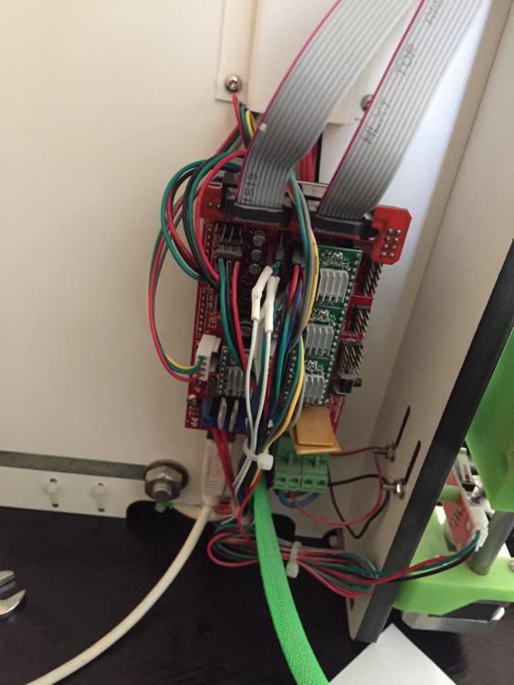

-
bonjour sylvain 33 ans materiel : prussa i3 type