Classement


Contenu populaire
Contenu avec la plus haute réputation dans 02/02/2020 Dans tous les contenus
-
Tuto pour trouver cura3 points
-
Je suis en train de pensé que tu te fou de ma gue... ta vis du pignon n'est pas sur le meplat de l'axe moteur2 points
-
T'en fait pas, ta tous ton temps. Juste il me tente bien aussi du coup ...1 point
-
Pour les vibrations si tu a peur que ça ai un impact sur l'imprimante, tu peut lui mettre des patins anti-vibration (voir les imprimer avec du tpu ou autres filaments flex). Pour l'occas je pense qu'il faut tout regarder et si possible aller la voir sur place et la tester, ce serait con d'avoir un axe tordu ou autre merde très chiante, pour moi faut fuir les imprimantes trop bidouillée (je parle pas des améliorations top de certains mais celle là sont rarement à vendre), à vouloir trop "améliorer" on fait pire et revenir en arrière n'est pas toujours possible.1 point
-
@Locouarn : dés que j'ai un moment je teste ça : mks sbase + tb6600 + tft 32. En ce moment mes préoccupations sont ailleurs et j'ai mis en suspend le projet de ma cnc un peu plus "sérieuse".1 point
-
Oui je sais bien mais pour éviter les bêtises je voulais avancer pas à pas.Partout où je regarde les personnes fournissent les fichiers mais pour Marlin 2.0.1 il faut croire que personne n'a encore fait cette config Et pardon pour l'affichage du fichier en entier :x Configuration.h Configuration_adv.h1 point
-
Dans le fichier que tu as joint, le TOUCH_MI n'est pas activé Plutôt que d'incorporer ton fichier, tu devrais le mettre en pièce-jointe (plus facile à récupérer pour l'analyser). Mets en PJ, tes deux fichiers (configuration.h et configuration_adv.h) utilisés pour compiler qui t'ont provoqués l'erreur1 point
-
salut non j'ai continué ca me fait chaud au coeur de voir que ca vous fait plaisir de me revoir https://www.amazon.fr/gp/product/B07XC29MZC/ref=ppx_yo_dt_b_asin_title_o07_s00?ie=UTF8&psc=1 la j'imprime des limaces je vais faire une video les moteurs s'entendent plus1 point
-
/** * Marlin 3D Printer Firmware * Copyright (c) 2019 MarlinFirmware [https://github.com/MarlinFirmware/Marlin] * * Based on Sprinter and grbl. * Copyright (c) 2011 Camiel Gubbels / Erik van der Zalm * * This program is free software: you can redistribute it and/or modify * it under the terms of the GNU General Public License as published by * the Free Software Foundation, either version 3 of the License, or * (at your option) any later version. * * This program is distributed in the hope that it will be useful, * but WITHOUT ANY WARRANTY; without even the implied warranty of * MERCHANTABILITY or FITNESS FOR A PARTICULAR PURPOSE. See the * GNU General Public License for more details. * * You should have received a copy of the GNU General Public License * along with this program. If not, see <http://www.gnu.org/licenses/>. * */ #pragma once /** * Configuration.h * * Basic settings such as: * * - Type of electronics * - Type of temperature sensor * - Printer geometry * - Endstop configuration * - LCD controller * - Extra features * * Advanced settings can be found in Configuration_adv.h * */ #define CONFIGURATION_H_VERSION 020000 //=========================================================================== //============================= Getting Started ============================= //=========================================================================== /** * Here are some standard links for getting your machine calibrated: * * http://reprap.org/wiki/Calibration * http://youtu.be/wAL9d7FgInk * http://calculator.josefprusa.cz * http://reprap.org/wiki/Triffid_Hunter%27s_Calibration_Guide * http://www.thingiverse.com/thing:5573 * https://sites.google.com/site/repraplogphase/calibration-of-your-reprap * http://www.thingiverse.com/thing:298812 */ //=========================================================================== //============================= DELTA Printer =============================== //=========================================================================== // For a Delta printer start with one of the configuration files in the // config/examples/delta directory and customize for your machine. // //=========================================================================== //============================= SCARA Printer =============================== //=========================================================================== // For a SCARA printer start with the configuration files in // config/examples/SCARA and customize for your machine. // // @section info // Author info of this build printed to the host during boot and M115 #define STRING_CONFIG_H_AUTHOR "(thisiskeithb, Ender-3)" // Who made the changes. //#define CUSTOM_VERSION_FILE Version.h // Path from the root directory (no quotes) /** * *** VENDORS PLEASE READ *** * * Marlin allows you to add a custom boot image for Graphical LCDs. * With this option Marlin will first show your custom screen followed * by the standard Marlin logo with version number and web URL. * * We encourage you to take advantage of this new feature and we also * respectfully request that you retain the unmodified Marlin boot screen. */ // Show the Marlin bootscreen on startup. ** ENABLE FOR PRODUCTION ** //#define SHOW_BOOTSCREEN // Show the bitmap in Marlin/_Bootscreen.h on startup. //#define SHOW_CUSTOM_BOOTSCREEN // Show the bitmap in Marlin/_Statusscreen.h on the status screen. #define CUSTOM_STATUS_SCREEN_IMAGE // @section machine /** * Select the serial port on the board to use for communication with the host. * This allows the connection of wireless adapters (for instance) to non-default port pins. * Note: The first serial port (-1 or 0) will always be used by the Arduino bootloader. * * :[-1, 0, 1, 2, 3, 4, 5, 6, 7] */ #define SERIAL_PORT 0 /** * Select a secondary serial port on the board to use for communication with the host. * This allows the connection of wireless adapters (for instance) to non-default port pins. * Serial port -1 is the USB emulated serial port, if available. * * :[-1, 0, 1, 2, 3, 4, 5, 6, 7] */ //#define SERIAL_PORT_2 -1 /** * This setting determines the communication speed of the printer. * * 250000 works in most cases, but you might try a lower speed if * you commonly experience drop-outs during host printing. * You may try up to 1000000 to speed up SD file transfer. * * :[2400, 9600, 19200, 38400, 57600, 115200, 250000, 500000, 1000000] */ #define BAUDRATE 115200 // Enable the Bluetooth serial interface on AT90USB devices //#define BLUETOOTH // Choose the name from boards.h that matches your setup #ifndef MOTHERBOARD #define MOTHERBOARD BOARD_MELZI_CREALITY #endif // Name displayed in the LCD "Ready" message and Info menu #define CUSTOM_MACHINE_NAME "Ender3" // Printer's unique ID, used by some programs to differentiate between machines. // Choose your own or use a service like http://www.uuidgenerator.net/version4 //#define MACHINE_UUID "00000000-0000-0000-0000-000000000000" // @section extruder // This defines the number of extruders // :[1, 2, 3, 4, 5, 6] #define EXTRUDERS 1 // Generally expected filament diameter (1.75, 2.85, 3.0, ...). Used for Volumetric, Filament Width Sensor, etc. #define DEFAULT_NOMINAL_FILAMENT_DIA 1.75 // For Cyclops or any "multi-extruder" that shares a single nozzle. //#define SINGLENOZZLE /** * Průša MK2 Single Nozzle Multi-Material Multiplexer, and variants. * * This device allows one stepper driver on a control board to drive * two to eight stepper motors, one at a time, in a manner suitable * for extruders. * * This option only allows the multiplexer to switch on tool-change. * Additional options to configure custom E moves are pending. */ //#define MK2_MULTIPLEXER #if ENABLED(MK2_MULTIPLEXER) // Override the default DIO selector pins here, if needed. // Some pins files may provide defaults for these pins. //#define E_MUX0_PIN 40 // Always Required //#define E_MUX1_PIN 42 // Needed for 3 to 8 inputs //#define E_MUX2_PIN 44 // Needed for 5 to 8 inputs #endif /** * Prusa Multi-Material Unit v2 * * Requires NOZZLE_PARK_FEATURE to park print head in case MMU unit fails. * Requires EXTRUDERS = 5 * * For additional configuration see Configuration_adv.h */ //#define PRUSA_MMU2 // A dual extruder that uses a single stepper motor //#define SWITCHING_EXTRUDER #if ENABLED(SWITCHING_EXTRUDER) #define SWITCHING_EXTRUDER_SERVO_NR 0 #define SWITCHING_EXTRUDER_SERVO_ANGLES { 0, 90 } // Angles for E0, E1[, E2, E3] #if EXTRUDERS > 3 #define SWITCHING_EXTRUDER_E23_SERVO_NR 1 #endif #endif // A dual-nozzle that uses a servomotor to raise/lower one (or both) of the nozzles //#define SWITCHING_NOZZLE #if ENABLED(SWITCHING_NOZZLE) #define SWITCHING_NOZZLE_SERVO_NR 0 //#define SWITCHING_NOZZLE_E1_SERVO_NR 1 // If two servos are used, the index of the second #define SWITCHING_NOZZLE_SERVO_ANGLES { 0, 90 } // Angles for E0, E1 (single servo) or lowered/raised (dual servo) #endif /** * Two separate X-carriages with extruders that connect to a moving part * via a solenoid docking mechanism. Requires SOL1_PIN and SOL2_PIN. */ //#define PARKING_EXTRUDER /** * Two separate X-carriages with extruders that connect to a moving part * via a magnetic docking mechanism using movements and no solenoid * * project : https://www.thingiverse.com/thing:3080893 * movements : https://youtu.be/0xCEiG9VS3k * https://youtu.be/Bqbcs0CU2FE */ //#define MAGNETIC_PARKING_EXTRUDER #if EITHER(PARKING_EXTRUDER, MAGNETIC_PARKING_EXTRUDER) #define PARKING_EXTRUDER_PARKING_X { -78, 184 } // X positions for parking the extruders #define PARKING_EXTRUDER_GRAB_DISTANCE 1 // (mm) Distance to move beyond the parking point to grab the extruder //#define MANUAL_SOLENOID_CONTROL // Manual control of docking solenoids with M380 S / M381 #if ENABLED(PARKING_EXTRUDER) #define PARKING_EXTRUDER_SOLENOIDS_INVERT // If enabled, the solenoid is NOT magnetized with applied voltage #define PARKING_EXTRUDER_SOLENOIDS_PINS_ACTIVE LOW // LOW or HIGH pin signal energizes the coil #define PARKING_EXTRUDER_SOLENOIDS_DELAY 250 // (ms) Delay for magnetic field. No delay if 0 or not defined. //#define MANUAL_SOLENOID_CONTROL // Manual control of docking solenoids with M380 S / M381 #elif ENABLED(MAGNETIC_PARKING_EXTRUDER) #define MPE_FAST_SPEED 9000 // (mm/m) Speed for travel before last distance point #define MPE_SLOW_SPEED 4500 // (mm/m) Speed for last distance travel to park and couple #define MPE_TRAVEL_DISTANCE 10 // (mm) Last distance point #define MPE_COMPENSATION 0 // Offset Compensation -1 , 0 , 1 (multiplier) only for coupling #endif #endif /** * Switching Toolhead * * Support for swappable and dockable toolheads, such as * the E3D Tool Changer. Toolheads are locked with a servo. */ //#define SWITCHING_TOOLHEAD /** * Magnetic Switching Toolhead * * Support swappable and dockable toolheads with a magnetic * docking mechanism using movement and no servo. */ //#define MAGNETIC_SWITCHING_TOOLHEAD /** * Electromagnetic Switching Toolhead * * Parking for CoreXY / HBot kinematics. * Toolheads are parked at one edge and held with an electromagnet. * Supports more than 2 Toolheads. See https://youtu.be/JolbsAKTKf4 */ //#define ELECTROMAGNETIC_SWITCHING_TOOLHEAD #if ANY(SWITCHING_TOOLHEAD, MAGNETIC_SWITCHING_TOOLHEAD, ELECTROMAGNETIC_SWITCHING_TOOLHEAD) #define SWITCHING_TOOLHEAD_Y_POS 235 // (mm) Y position of the toolhead dock #define SWITCHING_TOOLHEAD_Y_SECURITY 10 // (mm) Security distance Y axis #define SWITCHING_TOOLHEAD_Y_CLEAR 60 // (mm) Minimum distance from dock for unobstructed X axis #define SWITCHING_TOOLHEAD_X_POS { 215, 0 } // (mm) X positions for parking the extruders #if ENABLED(SWITCHING_TOOLHEAD) #define SWITCHING_TOOLHEAD_SERVO_NR 2 // Index of the servo connector #define SWITCHING_TOOLHEAD_SERVO_ANGLES { 0, 180 } // (degrees) Angles for Lock, Unlock #elif ENABLED(MAGNETIC_SWITCHING_TOOLHEAD) #define SWITCHING_TOOLHEAD_Y_RELEASE 5 // (mm) Security distance Y axis #define SWITCHING_TOOLHEAD_X_SECURITY { 90, 150 } // (mm) Security distance X axis (T0,T1) //#define PRIME_BEFORE_REMOVE // Prime the nozzle before release from the dock #if ENABLED(PRIME_BEFORE_REMOVE) #define SWITCHING_TOOLHEAD_PRIME_MM 20 // (mm) Extruder prime length #define SWITCHING_TOOLHEAD_RETRACT_MM 10 // (mm) Retract after priming length #define SWITCHING_TOOLHEAD_PRIME_FEEDRATE 300 // (mm/m) Extruder prime feedrate #define SWITCHING_TOOLHEAD_RETRACT_FEEDRATE 2400 // (mm/m) Extruder retract feedrate #endif #elif ENABLED(ELECTROMAGNETIC_SWITCHING_TOOLHEAD) #define SWITCHING_TOOLHEAD_Z_HOP 2 // (mm) Z raise for switching #endif #endif /** * "Mixing Extruder" * - Adds G-codes M163 and M164 to set and "commit" the current mix factors. * - Extends the stepping routines to move multiple steppers in proportion to the mix. * - Optional support for Repetier Firmware's 'M164 S<index>' supporting virtual tools. * - This implementation supports up to two mixing extruders. * - Enable DIRECT_MIXING_IN_G1 for M165 and mixing in G1 (from Pia Taubert's reference implementation). */ //#define MIXING_EXTRUDER #if ENABLED(MIXING_EXTRUDER) #define MIXING_STEPPERS 2 // Number of steppers in your mixing extruder #define MIXING_VIRTUAL_TOOLS 16 // Use the Virtual Tool method with M163 and M164 //#define DIRECT_MIXING_IN_G1 // Allow ABCDHI mix factors in G1 movement commands //#define GRADIENT_MIX // Support for gradient mixing with M166 and LCD #if ENABLED(GRADIENT_MIX) //#define GRADIENT_VTOOL // Add M166 T to use a V-tool index as a Gradient alias #endif #endif // Offset of the extruders (uncomment if using more than one and relying on firmware to position when changing). // The offset has to be X=0, Y=0 for the extruder 0 hotend (default extruder). // For the other hotends it is their distance from the extruder 0 hotend. //#define HOTEND_OFFSET_X { 0.0, 20.00 } // (mm) relative X-offset for each nozzle //#define HOTEND_OFFSET_Y { 0.0, 5.00 } // (mm) relative Y-offset for each nozzle //#define HOTEND_OFFSET_Z { 0.0, 0.00 } // (mm) relative Z-offset for each nozzle // @section machine /** * Power Supply Control * * Enable and connect the power supply to the PS_ON_PIN. * Specify whether the power supply is active HIGH or active LOW. */ //#define PSU_CONTROL //#define PSU_NAME "Power Supply" #if ENABLED(PSU_CONTROL) #define PSU_ACTIVE_HIGH false // Set 'false' for ATX, 'true' for X-Box //#define PSU_DEFAULT_OFF // Keep power off until enabled directly with M80 //#define PSU_POWERUP_DELAY 100 // (ms) Delay for the PSU to warm up to full power //#define AUTO_POWER_CONTROL // Enable automatic control of the PS_ON pin #if ENABLED(AUTO_POWER_CONTROL) #define AUTO_POWER_FANS // Turn on PSU if fans need power #define AUTO_POWER_E_FANS #define AUTO_POWER_CONTROLLERFAN #define AUTO_POWER_CHAMBER_FAN //#define AUTO_POWER_E_TEMP 50 // (°C) Turn on PSU over this temperature //#define AUTO_POWER_CHAMBER_TEMP 30 // (°C) Turn on PSU over this temperature #define POWER_TIMEOUT 30 #endif #endif // @section temperature //=========================================================================== //============================= Thermal Settings ============================ //=========================================================================== /** * --NORMAL IS 4.7kohm PULLUP!-- 1kohm pullup can be used on hotend sensor, using correct resistor and table * * Temperature sensors available: * * -5 : PT100 / PT1000 with MAX31865 (only for sensors 0-1) * -3 : thermocouple with MAX31855 (only for sensors 0-1) * -2 : thermocouple with MAX6675 (only for sensors 0-1) * -4 : thermocouple with AD8495 * -1 : thermocouple with AD595 * 0 : not used * 1 : 100k thermistor - best choice for EPCOS 100k (4.7k pullup) * 331 : (3.3V scaled thermistor 1 table) * 2 : 200k thermistor - ATC Semitec 204GT-2 (4.7k pullup) * 3 : Mendel-parts thermistor (4.7k pullup) * 4 : 10k thermistor !! do not use it for a hotend. It gives bad resolution at high temp. !! * 5 : 100K thermistor - ATC Semitec 104GT-2/104NT-4-R025H42G (Used in ParCan & J-Head) (4.7k pullup) * 501 : 100K Zonestar (Tronxy X3A) Thermistor * 512 : 100k RPW-Ultra hotend thermistor (4.7k pullup) * 6 : 100k EPCOS - Not as accurate as table 1 (created using a fluke thermocouple) (4.7k pullup) * 7 : 100k Honeywell thermistor 135-104LAG-J01 (4.7k pullup) * 71 : 100k Honeywell thermistor 135-104LAF-J01 (4.7k pullup) * 8 : 100k 0603 SMD Vishay NTCS0603E3104FXT (4.7k pullup) * 9 : 100k GE Sensing AL03006-58.2K-97-G1 (4.7k pullup) * 10 : 100k RS thermistor 198-961 (4.7k pullup) * 11 : 100k beta 3950 1% thermistor (4.7k pullup) * 12 : 100k 0603 SMD Vishay NTCS0603E3104FXT (4.7k pullup) (calibrated for Makibox hot bed) * 13 : 100k Hisens 3950 1% up to 300°C for hotend "Simple ONE " & "Hotend "All In ONE" * 15 : 100k thermistor calibration for JGAurora A5 hotend * 18 : ATC Semitec 204GT-2 (4.7k pullup) Dagoma.Fr - MKS_Base_DKU001327 * 20 : Pt100 with circuit in the Ultimainboard V2.x * 201 : Pt100 with circuit in Overlord, similar to Ultimainboard V2.x * 60 : 100k Maker's Tool Works Kapton Bed Thermistor beta=3950 * 61 : 100k Formbot / Vivedino 3950 350C thermistor 4.7k pullup * 66 : 4.7M High Temperature thermistor from Dyze Design * 67 : 450C thermistor from SliceEngineering * 70 : the 100K thermistor found in the bq Hephestos 2 * 75 : 100k Generic Silicon Heat Pad with NTC 100K MGB18-104F39050L32 thermistor * 99 : 100k thermistor with a 10K pull-up resistor (found on some Wanhao i3 machines) * * 1k ohm pullup tables - This is atypical, and requires changing out the 4.7k pullup for 1k. * (but gives greater accuracy and more stable PID) * 51 : 100k thermistor - EPCOS (1k pullup) * 52 : 200k thermistor - ATC Semitec 204GT-2 (1k pullup) * 55 : 100k thermistor - ATC Semitec 104GT-2 (Used in ParCan & J-Head) (1k pullup) * * 1047 : Pt1000 with 4k7 pullup * 1010 : Pt1000 with 1k pullup (non standard) * 147 : Pt100 with 4k7 pullup * 110 : Pt100 with 1k pullup (non standard) * * 1000 : Custom - Specify parameters in Configuration_adv.h * * Use these for Testing or Development purposes. NEVER for production machine. * 998 : Dummy Table that ALWAYS reads 25°C or the temperature defined below. * 999 : Dummy Table that ALWAYS reads 100°C or the temperature defined below. */ #define TEMP_SENSOR_0 1 #define TEMP_SENSOR_1 0 #define TEMP_SENSOR_2 0 #define TEMP_SENSOR_3 0 #define TEMP_SENSOR_4 0 #define TEMP_SENSOR_5 0 #define TEMP_SENSOR_BED 1 #define TEMP_SENSOR_CHAMBER 0 // Dummy thermistor constant temperature readings, for use with 998 and 999 #define DUMMY_THERMISTOR_998_VALUE 25 #define DUMMY_THERMISTOR_999_VALUE 100 // Use temp sensor 1 as a redundant sensor with sensor 0. If the readings // from the two sensors differ too much the print will be aborted. //#define TEMP_SENSOR_1_AS_REDUNDANT #define MAX_REDUNDANT_TEMP_SENSOR_DIFF 10 #define TEMP_RESIDENCY_TIME 10 // (seconds) Time to wait for hotend to "settle" in M109 #define TEMP_WINDOW 1 // (°C) Temperature proximity for the "temperature reached" timer #define TEMP_HYSTERESIS 3 // (°C) Temperature proximity considered "close enough" to the target #define TEMP_BED_RESIDENCY_TIME 10 // (seconds) Time to wait for bed to "settle" in M190 #define TEMP_BED_WINDOW 1 // (°C) Temperature proximity for the "temperature reached" timer #define TEMP_BED_HYSTERESIS 3 // (°C) Temperature proximity considered "close enough" to the target // Below this temperature the heater will be switched off // because it probably indicates a broken thermistor wire. #define HEATER_0_MINTEMP 5 #define HEATER_1_MINTEMP 5 #define HEATER_2_MINTEMP 5 #define HEATER_3_MINTEMP 5 #define HEATER_4_MINTEMP 5 #define HEATER_5_MINTEMP 5 #define BED_MINTEMP 5 // Above this temperature the heater will be switched off. // This can protect components from overheating, but NOT from shorts and failures. // (Use MINTEMP for thermistor short/failure protection.) #define HEATER_0_MAXTEMP 275 #define HEATER_1_MAXTEMP 275 #define HEATER_2_MAXTEMP 275 #define HEATER_3_MAXTEMP 275 #define HEATER_4_MAXTEMP 275 #define HEATER_5_MAXTEMP 275 #define BED_MAXTEMP 125 //=========================================================================== //============================= PID Settings ================================ //=========================================================================== // PID Tuning Guide here: http://reprap.org/wiki/PID_Tuning // Comment the following line to disable PID and enable bang-bang. #define PIDTEMP #define BANG_MAX 255 // Limits current to nozzle while in bang-bang mode; 255=full current #define PID_MAX BANG_MAX // Limits current to nozzle while PID is active (see PID_FUNCTIONAL_RANGE below); 255=full current #define PID_K1 0.95 // Smoothing factor within any PID loop #if ENABLED(PIDTEMP) #define PID_EDIT_MENU // Add PID editing to the "Advanced Settings" menu. (~700 bytes of PROGMEM) #define PID_AUTOTUNE_MENU // Add PID auto-tuning to the "Advanced Settings" menu. (~250 bytes of PROGMEM) //#define PID_DEBUG // Sends debug data to the serial port. //#define PID_OPENLOOP 1 // Puts PID in open loop. M104/M140 sets the output power from 0 to PID_MAX //#define SLOW_PWM_HEATERS // PWM with very low frequency (roughly 0.125Hz=8s) and minimum state time of approximately 1s useful for heaters driven by a relay //#define PID_PARAMS_PER_HOTEND // Uses separate PID parameters for each extruder (useful for mismatched extruders) // Set/get with gcode: M301 E[extruder number, 0-2] #define PID_FUNCTIONAL_RANGE 10 // If the temperature difference between the target temperature and the actual temperature // is more than PID_FUNCTIONAL_RANGE then the PID will be shut off and the heater will be set to min/max. // If you are using a pre-configured hotend then you can use one of the value sets by uncommenting it // Creality Ender-3 #define DEFAULT_Kp 21.73 #define DEFAULT_Ki 1.54 #define DEFAULT_Kd 76.55 // Ultimaker //#define DEFAULT_Kp 22.2 //#define DEFAULT_Ki 1.08 //#define DEFAULT_Kd 114 // MakerGear //#define DEFAULT_Kp 7.0 //#define DEFAULT_Ki 0.1 //#define DEFAULT_Kd 12 // Mendel Parts V9 on 12V //#define DEFAULT_Kp 63.0 //#define DEFAULT_Ki 2.25 //#define DEFAULT_Kd 440 #endif // PIDTEMP //=========================================================================== //====================== PID > Bed Temperature Control ====================== //=========================================================================== /** * PID Bed Heating * * If this option is enabled set PID constants below. * If this option is disabled, bang-bang will be used and BED_LIMIT_SWITCHING will enable hysteresis. * * The PID frequency will be the same as the extruder PWM. * If PID_dT is the default, and correct for the hardware/configuration, that means 7.689Hz, * which is fine for driving a square wave into a resistive load and does not significantly * impact FET heating. This also works fine on a Fotek SSR-10DA Solid State Relay into a 250W * heater. If your configuration is significantly different than this and you don't understand * the issues involved, don't use bed PID until someone else verifies that your hardware works. */ //#define PIDTEMPBED //#define BED_LIMIT_SWITCHING /** * Max Bed Power * Applies to all forms of bed control (PID, bang-bang, and bang-bang with hysteresis). * When set to any value below 255, enables a form of PWM to the bed that acts like a divider * so don't use it unless you are OK with PWM on your bed. (See the comment on enabling PIDTEMPBED) */ #define MAX_BED_POWER 255 // limits duty cycle to bed; 255=full current #if ENABLED(PIDTEMPBED) //#define MIN_BED_POWER 0 //#define PID_BED_DEBUG // Sends debug data to the serial port. //120V 250W silicone heater into 4mm borosilicate (MendelMax 1.5+) //from FOPDT model - kp=.39 Tp=405 Tdead=66, Tc set to 79.2, aggressive factor of .15 (vs .1, 1, 10) #define DEFAULT_bedKp 10.00 #define DEFAULT_bedKi .023 #define DEFAULT_bedKd 305.4 //120V 250W silicone heater into 4mm borosilicate (MendelMax 1.5+) //from pidautotune //#define DEFAULT_bedKp 97.1 //#define DEFAULT_bedKi 1.41 //#define DEFAULT_bedKd 1675.16 // FIND YOUR OWN: "M303 E-1 C8 S90" to run autotune on the bed at 90 degreesC for 8 cycles. #endif // PIDTEMPBED // @section extruder /** * Prevent extrusion if the temperature is below EXTRUDE_MINTEMP. * Add M302 to set the minimum extrusion temperature and/or turn * cold extrusion prevention on and off. * * *** IT IS HIGHLY RECOMMENDED TO LEAVE THIS OPTION ENABLED! *** */ #define PREVENT_COLD_EXTRUSION #define EXTRUDE_MINTEMP 170 /** * Prevent a single extrusion longer than EXTRUDE_MAXLENGTH. * Note: For Bowden Extruders make this large enough to allow load/unload. */ #define PREVENT_LENGTHY_EXTRUDE #define EXTRUDE_MAXLENGTH 200 //=========================================================================== //======================== Thermal Runaway Protection ======================= //=========================================================================== /** * Thermal Protection provides additional protection to your printer from damage * and fire. Marlin always includes safe min and max temperature ranges which * protect against a broken or disconnected thermistor wire. * * The issue: If a thermistor falls out, it will report the much lower * temperature of the air in the room, and the the firmware will keep * the heater on. * * If you get "Thermal Runaway" or "Heating failed" errors the * details can be tuned in Configuration_adv.h */ #define THERMAL_PROTECTION_HOTENDS // Enable thermal protection for all extruders #define THERMAL_PROTECTION_BED // Enable thermal protection for the heated bed #define THERMAL_PROTECTION_CHAMBER // Enable thermal protection for the heated chamber //=========================================================================== //============================= Mechanical Settings ========================= //=========================================================================== // @section machine // Uncomment one of these options to enable CoreXY, CoreXZ, or CoreYZ kinematics // either in the usual order or reversed //#define COREXY //#define COREXZ //#define COREYZ //#define COREYX //#define COREZX //#define COREZY //=========================================================================== //============================== Endstop Settings =========================== //=========================================================================== // @section homing // Specify here all the endstop connectors that are connected to any endstop or probe. // Almost all printers will be using one per axis. Probes will use one or more of the // extra connectors. Leave undefined any used for non-endstop and non-probe purposes. #define USE_XMIN_PLUG #define USE_YMIN_PLUG #define USE_ZMIN_PLUG //#define USE_XMAX_PLUG //#define USE_YMAX_PLUG //#define USE_ZMAX_PLUG // Enable pullup for all endstops to prevent a floating state #define ENDSTOPPULLUPS #if DISABLED(ENDSTOPPULLUPS) // Disable ENDSTOPPULLUPS to set pullups individually //#define ENDSTOPPULLUP_XMAX //#define ENDSTOPPULLUP_YMAX //#define ENDSTOPPULLUP_ZMAX //#define ENDSTOPPULLUP_XMIN //#define ENDSTOPPULLUP_YMIN //#define ENDSTOPPULLUP_ZMIN //#define ENDSTOPPULLUP_ZMIN_PROBE #endif // Enable pulldown for all endstops to prevent a floating state //#define ENDSTOPPULLDOWNS #if DISABLED(ENDSTOPPULLDOWNS) // Disable ENDSTOPPULLDOWNS to set pulldowns individually //#define ENDSTOPPULLDOWN_XMAX //#define ENDSTOPPULLDOWN_YMAX //#define ENDSTOPPULLDOWN_ZMAX //#define ENDSTOPPULLDOWN_XMIN //#define ENDSTOPPULLDOWN_YMIN //#define ENDSTOPPULLDOWN_ZMIN //#define ENDSTOPPULLDOWN_ZMIN_PROBE #endif // Mechanical endstop with COM to ground and NC to Signal uses "false" here (most common setup). #define X_MIN_ENDSTOP_INVERTING false // Set to true to invert the logic of the endstop. #define Y_MIN_ENDSTOP_INVERTING false // Set to true to invert the logic of the endstop. #define Z_MIN_ENDSTOP_INVERTING false // Set to true to invert the logic of the endstop. #define X_MAX_ENDSTOP_INVERTING false // Set to true to invert the logic of the endstop. #define Y_MAX_ENDSTOP_INVERTING false // Set to true to invert the logic of the endstop. #define Z_MAX_ENDSTOP_INVERTING false // Set to true to invert the logic of the endstop. #define Z_MIN_PROBE_ENDSTOP_INVERTING false // Set to true to invert the logic of the probe. /** * Stepper Drivers * * These settings allow Marlin to tune stepper driver timing and enable advanced options for * stepper drivers that support them. You may also override timing options in Configuration_adv.h. * * A4988 is assumed for unspecified drivers. * * Options: A4988, A5984, DRV8825, LV8729, L6470, TB6560, TB6600, TMC2100, * TMC2130, TMC2130_STANDALONE, TMC2160, TMC2160_STANDALONE, * TMC2208, TMC2208_STANDALONE, TMC2209, TMC2209_STANDALONE, * TMC26X, TMC26X_STANDALONE, TMC2660, TMC2660_STANDALONE, * TMC5130, TMC5130_STANDALONE, TMC5160, TMC5160_STANDALONE * :['A4988', 'A5984', 'DRV8825', 'LV8729', 'L6470', 'TB6560', 'TB6600', 'TMC2100', 'TMC2130', 'TMC2130_STANDALONE', 'TMC2160', 'TMC2160_STANDALONE', 'TMC2208', 'TMC2208_STANDALONE', 'TMC2209', 'TMC2209_STANDALONE', 'TMC26X', 'TMC26X_STANDALONE', 'TMC2660', 'TMC2660_STANDALONE', 'TMC5130', 'TMC5130_STANDALONE', 'TMC5160', 'TMC5160_STANDALONE'] */ //#define X_DRIVER_TYPE A4988 //#define Y_DRIVER_TYPE A4988 //#define Z_DRIVER_TYPE A4988 //#define X2_DRIVER_TYPE A4988 //#define Y2_DRIVER_TYPE A4988 //#define Z2_DRIVER_TYPE A4988 //#define Z3_DRIVER_TYPE A4988 //#define E0_DRIVER_TYPE A4988 //#define E1_DRIVER_TYPE A4988 //#define E2_DRIVER_TYPE A4988 //#define E3_DRIVER_TYPE A4988 //#define E4_DRIVER_TYPE A4988 //#define E5_DRIVER_TYPE A4988 // Enable this feature if all enabled endstop pins are interrupt-capable. // This will remove the need to poll the interrupt pins, saving many CPU cycles. //#define ENDSTOP_INTERRUPTS_FEATURE /** * Endstop Noise Threshold * * Enable if your probe or endstops falsely trigger due to noise. * * - Higher values may affect repeatability or accuracy of some bed probes. * - To fix noise install a 100nF ceramic capacitor inline with the switch. * - This feature is not required for common micro-switches mounted on PCBs * based on the Makerbot design, which already have the 100nF capacitor. * * :[2,3,4,5,6,7] */ //#define ENDSTOP_NOISE_THRESHOLD 2 //============================================================================= //============================== Movement Settings ============================ //============================================================================= // @section motion /** * Default Settings * * These settings can be reset by M502 * * Note that if EEPROM is enabled, saved values will override these. */ /** * With this option each E stepper can have its own factors for the * following movement settings. If fewer factors are given than the * total number of extruders, the last value applies to the rest. */ //#define DISTINCT_E_FACTORS /** * Default Axis Steps Per Unit (steps/mm) * Override with M92 * X, Y, Z, E0 [, E1[, E2...]] */ #define DEFAULT_AXIS_STEPS_PER_UNIT { 80, 80, 400, 93 } /** * Default Max Feed Rate (mm/s) * Override with M203 * X, Y, Z, E0 [, E1[, E2...]] */ #define DEFAULT_MAX_FEEDRATE { 500, 500, 5, 25 } //#define LIMITED_MAX_FR_EDITING // Limit edit via M203 or LCD to DEFAULT_MAX_FEEDRATE * 2 #if ENABLED(LIMITED_MAX_FR_EDITING) #define MAX_FEEDRATE_EDIT_VALUES { 600, 600, 10, 50 } // ...or, set your own edit limits #endif /** * Default Max Acceleration (change/s) change = mm/s * (Maximum start speed for accelerated moves) * Override with M201 * X, Y, Z, E0 [, E1[, E2...]] */ #define DEFAULT_MAX_ACCELERATION { 500, 500, 100, 5000 } //#define LIMITED_MAX_ACCEL_EDITING // Limit edit via M201 or LCD to DEFAULT_MAX_ACCELERATION * 2 #if ENABLED(LIMITED_MAX_ACCEL_EDITING) #define MAX_ACCEL_EDIT_VALUES { 6000, 6000, 200, 20000 } // ...or, set your own edit limits #endif /** * Default Acceleration (change/s) change = mm/s * Override with M204 * * M204 P Acceleration * M204 R Retract Acceleration * M204 T Travel Acceleration */ #define DEFAULT_ACCELERATION 500 // X, Y, Z and E acceleration for printing moves #define DEFAULT_RETRACT_ACCELERATION 500 // E acceleration for retracts #define DEFAULT_TRAVEL_ACCELERATION 500 // X, Y, Z acceleration for travel (non printing) moves /** * Default Jerk limits (mm/s) * Override with M205 X Y Z E * * "Jerk" specifies the minimum speed change that requires acceleration. * When changing speed and direction, if the difference is less than the * value set here, it may happen instantaneously. */ //#define CLASSIC_JERK #if ENABLED(CLASSIC_JERK) #define DEFAULT_XJERK 10.0 #define DEFAULT_YJERK 10.0 #define DEFAULT_ZJERK 0.3 //#define LIMITED_JERK_EDITING // Limit edit via M205 or LCD to DEFAULT_aJERK * 2 #if ENABLED(LIMITED_JERK_EDITING) #define MAX_JERK_EDIT_VALUES { 20, 20, 0.6, 10 } // ...or, set your own edit limits #endif #endif #define DEFAULT_EJERK 5.0 // May be used by Linear Advance /** * Junction Deviation Factor * * See: * https://reprap.org/forum/read.php?1,739819 * http://blog.kyneticcnc.com/2018/10/computing-junction-deviation-for-marlin.html */ #if DISABLED(CLASSIC_JERK) #define JUNCTION_DEVIATION_MM 0.08 // (mm) Distance from real junction edge #endif /** * S-Curve Acceleration * * This option eliminates vibration during printing by fitting a Bézier * curve to move acceleration, producing much smoother direction changes. * * See https://github.com/synthetos/TinyG/wiki/Jerk-Controlled-Motion-Explained */ //#define S_CURVE_ACCELERATION //=========================================================================== //============================= Z Probe Options ============================= //=========================================================================== // @section probes // // See http://marlinfw.org/docs/configuration/probes.html // /** * Z_MIN_PROBE_USES_Z_MIN_ENDSTOP_PIN * * Enable this option for a probe connected to the Z Min endstop pin. */ #define Z_MIN_PROBE_USES_Z_MIN_ENDSTOP_PIN /** * Z_MIN_PROBE_PIN * * Define this pin if the probe is not connected to Z_MIN_PIN. * If not defined the default pin for the selected MOTHERBOARD * will be used. Most of the time the default is what you want. * * - The simplest option is to use a free endstop connector. * - Use 5V for powered (usually inductive) sensors. * * - RAMPS 1.3/1.4 boards may use the 5V, GND, and Aux4->D32 pin: * - For simple switches connect... * - normally-closed switches to GND and D32. * - normally-open switches to 5V and D32. * */ //#define Z_MIN_PROBE_PIN 32 // Pin 32 is the RAMPS default /** * Probe Type * * Allen Key Probes, Servo Probes, Z-Sled Probes, FIX_MOUNTED_PROBE, etc. * Activate one of these to use Auto Bed Leveling below. */ /** * The "Manual Probe" provides a means to do "Auto" Bed Leveling without a probe. * Use G29 repeatedly, adjusting the Z height at each point with movement commands * or (with LCD_BED_LEVELING) the LCD controller. */ //#define PROBE_MANUALLY //#define MANUAL_PROBE_START_Z 0.2 /** * A Fix-Mounted Probe either doesn't deploy or needs manual deployment. * (e.g., an inductive probe or a nozzle-based probe-switch.) */ #define FIX_MOUNTED_PROBE /** * Use the nozzle as the probe, as with a conductive * nozzle system or a piezo-electric smart effector. */ //#define NOZZLE_AS_PROBE /** * Z Servo Probe, such as an endstop switch on a rotating arm. */ //#define Z_PROBE_SERVO_NR 0 // Defaults to SERVO 0 connector. //#define Z_SERVO_ANGLES { 70, 0 } // Z Servo Deploy and Stow angles /** * The BLTouch probe uses a Hall effect sensor and emulates a servo. */ //#define BLTOUCH /** * Touch-MI Probe by hotends.fr * * This probe is deployed and activated by moving the X-axis to a magnet at the edge of the bed. * By default, the magnet is assumed to be on the left and activated by a home. If the magnet is * on the right, enable and set TOUCH_MI_DEPLOY_XPOS to the deploy position. * * Also requires: BABYSTEPPING, BABYSTEP_ZPROBE_OFFSET, Z_SAFE_HOMING, * and a minimum Z_HOMING_HEIGHT of 10. */ //#define TOUCH_MI_PROBE #if ENABLED(TOUCH_MI_PROBE) #define TOUCH_MI_RETRACT_Z 0.5 // Height at which the probe retracts //#define TOUCH_MI_DEPLOY_XPOS (X_MAX_BED + 2) // For a magnet on the right side of the bed //#define TOUCH_MI_MANUAL_DEPLOY // For manual deploy (LCD menu) #endif // A probe that is deployed and stowed with a solenoid pin (SOL1_PIN) //#define SOLENOID_PROBE // A sled-mounted probe like those designed by Charles Bell. //#define Z_PROBE_SLED //#define SLED_DOCKING_OFFSET 5 // The extra distance the X axis must travel to pickup the sled. 0 should be fine but you can push it further if you'd like. // A probe deployed by moving the x-axis, such as the Wilson II's rack-and-pinion probe designed by Marty Rice. //#define RACK_AND_PINION_PROBE #if ENABLED(RACK_AND_PINION_PROBE) #define Z_PROBE_DEPLOY_X X_MIN_POS #define Z_PROBE_RETRACT_X X_MAX_POS #endif // // For Z_PROBE_ALLEN_KEY see the Delta example configurations. // /** * Z Probe to nozzle (X,Y) offset, relative to (0, 0). * * In the following example the X and Y offsets are both positive: * * #define NOZZLE_TO_PROBE_OFFSET { 10, 10, 0 } * * +-- BACK ---+ * | | * L | (+) P | R <-- probe (20,20) * E | | I * F | (-) N (+) | G <-- nozzle (10,10) * T | | H * | (-) | T * | | * O-- FRONT --+ * (0,0) * * Specify a Probe position as { X, Y, Z } */ #define NOZZLE_TO_PROBE_OFFSET { -23, -46, 0 } // Certain types of probes need to stay away from edges #define MIN_PROBE_EDGE 10 // X and Y axis travel speed (mm/m) between probes #define XY_PROBE_SPEED 8000 // Feedrate (mm/m) for the first approach when double-probing (MULTIPLE_PROBING == 2) #define Z_PROBE_SPEED_FAST HOMING_FEEDRATE_Z // Feedrate (mm/m) for the "accurate" probe of each point #define Z_PROBE_SPEED_SLOW (Z_PROBE_SPEED_FAST / 2) /** * Multiple Probing * * You may get improved results by probing 2 or more times. * With EXTRA_PROBING the more atypical reading(s) will be disregarded. * * A total of 2 does fast/slow probes with a weighted average. * A total of 3 or more adds more slow probes, taking the average. */ //#define MULTIPLE_PROBING 2 //#define EXTRA_PROBING 1 /** * Z probes require clearance when deploying, stowing, and moving between * probe points to avoid hitting the bed and other hardware. * Servo-mounted probes require extra space for the arm to rotate. * Inductive probes need space to keep from triggering early. * * Use these settings to specify the distance (mm) to raise the probe (or * lower the bed). The values set here apply over and above any (negative) * probe Z Offset set with NOZZLE_TO_PROBE_OFFSET, M851, or the LCD. * Only integer values >= 1 are valid here. * * Example: `M851 Z-5` with a CLEARANCE of 4 => 9mm from bed to nozzle. * But: `M851 Z+1` with a CLEARANCE of 2 => 2mm from bed to nozzle. */ #define Z_CLEARANCE_DEPLOY_PROBE 10 // Z Clearance for Deploy/Stow #define Z_CLEARANCE_BETWEEN_PROBES 5 // Z Clearance between probe points #define Z_CLEARANCE_MULTI_PROBE 5 // Z Clearance between multiple probes //#define Z_AFTER_PROBING 5 // Z position after probing is done #define Z_PROBE_LOW_POINT -2 // Farthest distance below the trigger-point to go before stopping // For M851 give a range for adjusting the Z probe offset #define Z_PROBE_OFFSET_RANGE_MIN -20 #define Z_PROBE_OFFSET_RANGE_MAX 20 // Enable the M48 repeatability test to test probe accuracy //#define Z_MIN_PROBE_REPEATABILITY_TEST // Before deploy/stow pause for user confirmation //#define PAUSE_BEFORE_DEPLOY_STOW #if ENABLED(PAUSE_BEFORE_DEPLOY_STOW) //#define PAUSE_PROBE_DEPLOY_WHEN_TRIGGERED // For Manual Deploy Allenkey Probe #endif /** * Enable one or more of the following if probing seems unreliable. * Heaters and/or fans can be disabled during probing to minimize electrical * noise. A delay can also be added to allow noise and vibration to settle. * These options are most useful for the BLTouch probe, but may also improve * readings with inductive probes and piezo sensors. */ //#define PROBING_HEATERS_OFF // Turn heaters off when probing #if ENABLED(PROBING_HEATERS_OFF) //#define WAIT_FOR_BED_HEATER // Wait for bed to heat back up between probes (to improve accuracy) #endif //#define PROBING_FANS_OFF // Turn fans off when probing //#define PROBING_STEPPERS_OFF // Turn steppers off (unless needed to hold position) when probing //#define DELAY_BEFORE_PROBING 200 // (ms) To prevent vibrations from triggering piezo sensors // For Inverting Stepper Enable Pins (Active Low) use 0, Non Inverting (Active High) use 1 // :{ 0:'Low', 1:'High' } #define X_ENABLE_ON 0 #define Y_ENABLE_ON 0 #define Z_ENABLE_ON 0 #define E_ENABLE_ON 0 // For all extruders // Disables axis stepper immediately when it's not being used. // WARNING: When motors turn off there is a chance of losing position accuracy! #define DISABLE_X false #define DISABLE_Y false #define DISABLE_Z false // Warn on display about possibly reduced accuracy //#define DISABLE_REDUCED_ACCURACY_WARNING // @section extruder #define DISABLE_E false // For all extruders //#define DISABLE_INACTIVE_EXTRUDER // Keep only the active extruder enabled // @section machine // Invert the stepper direction. Change (or reverse the motor connector) if an axis goes the wrong way. #define INVERT_X_DIR true #define INVERT_Y_DIR true #define INVERT_Z_DIR false // @section extruder // For direct drive extruder v9 set to true, for geared extruder set to false. #define INVERT_E0_DIR true #define INVERT_E1_DIR false #define INVERT_E2_DIR false #define INVERT_E3_DIR false #define INVERT_E4_DIR false #define INVERT_E5_DIR false // @section homing //#define NO_MOTION_BEFORE_HOMING // Inhibit movement until all axes have been homed //#define UNKNOWN_Z_NO_RAISE // Don't raise Z (lower the bed) if Z is "unknown." For beds that fall when Z is powered off. #define Z_HOMING_HEIGHT 20 // (mm) Minimal Z height before homing (G28) for Z clearance above the bed, clamps, ... // Be sure you have this distance over your Z_MAX_POS in case. // Direction of endstops when homing; 1=MAX, -1=MIN // :[-1,1] #define X_HOME_DIR -1 #define Y_HOME_DIR -1 #define Z_HOME_DIR -1 // @section machine // The size of the print bed #define X_BED_SIZE 235 #define Y_BED_SIZE 235 // Travel limits (mm) after homing, corresponding to endstop positions. #define X_MIN_POS 0 #define Y_MIN_POS 0 #define Z_MIN_POS 0 #define X_MAX_POS X_BED_SIZE #define Y_MAX_POS Y_BED_SIZE #define Z_MAX_POS 250 /** * Software Endstops * * - Prevent moves outside the set machine bounds. * - Individual axes can be disabled, if desired. * - X and Y only apply to Cartesian robots. * - Use 'M211' to set software endstops on/off or report current state */ // Min software endstops constrain movement within minimum coordinate bounds #define MIN_SOFTWARE_ENDSTOPS #if ENABLED(MIN_SOFTWARE_ENDSTOPS) #define MIN_SOFTWARE_ENDSTOP_X #define MIN_SOFTWARE_ENDSTOP_Y #define MIN_SOFTWARE_ENDSTOP_Z #endif // Max software endstops constrain movement within maximum coordinate bounds #define MAX_SOFTWARE_ENDSTOPS #if ENABLED(MAX_SOFTWARE_ENDSTOPS) #define MAX_SOFTWARE_ENDSTOP_X #define MAX_SOFTWARE_ENDSTOP_Y #define MAX_SOFTWARE_ENDSTOP_Z #endif #if EITHER(MIN_SOFTWARE_ENDSTOPS, MAX_SOFTWARE_ENDSTOPS) //#define SOFT_ENDSTOPS_MENU_ITEM // Enable/Disable software endstops from the LCD #endif /** * Filament Runout Sensors * Mechanical or opto endstops are used to check for the presence of filament. * * RAMPS-based boards use SERVO3_PIN for the first runout sensor. * For other boards you may need to define FIL_RUNOUT_PIN, FIL_RUNOUT2_PIN, etc. * By default the firmware assumes HIGH=FILAMENT PRESENT. */ //#define FILAMENT_RUNOUT_SENSOR #if ENABLED(FILAMENT_RUNOUT_SENSOR) #define NUM_RUNOUT_SENSORS 1 // Number of sensors, up to one per extruder. Define a FIL_RUNOUT#_PIN for each. #define FIL_RUNOUT_INVERTING false // Set to true to invert the logic of the sensor. #define FIL_RUNOUT_PULLUP // Use internal pullup for filament runout pins. //#define FIL_RUNOUT_PULLDOWN // Use internal pulldown for filament runout pins. // Set one or more commands to execute on filament runout. // (After 'M412 H' Marlin will ask the host to handle the process.) #define FILAMENT_RUNOUT_SCRIPT "M600" // After a runout is detected, continue printing this length of filament // before executing the runout script. Useful for a sensor at the end of // a feed tube. Requires 4 bytes SRAM per sensor, plus 4 bytes overhead. //#define FILAMENT_RUNOUT_DISTANCE_MM 25 #ifdef FILAMENT_RUNOUT_DISTANCE_MM // Enable this option to use an encoder disc that toggles the runout pin // as the filament moves. (Be sure to set FILAMENT_RUNOUT_DISTANCE_MM // large enough to avoid false positives.) //#define FILAMENT_MOTION_SENSOR #endif #endif //=========================================================================== //=============================== Bed Leveling ============================== //=========================================================================== // @section calibrate /** * Choose one of the options below to enable G29 Bed Leveling. The parameters * and behavior of G29 will change depending on your selection. * * If using a Probe for Z Homing, enable Z_SAFE_HOMING also! * * - AUTO_BED_LEVELING_3POINT * Probe 3 arbitrary points on the bed (that aren't collinear) * You specify the XY coordinates of all 3 points. * The result is a single tilted plane. Best for a flat bed. * * - AUTO_BED_LEVELING_LINEAR * Probe several points in a grid. * You specify the rectangle and the density of sample points. * The result is a single tilted plane. Best for a flat bed. * * - AUTO_BED_LEVELING_BILINEAR * Probe several points in a grid. * You specify the rectangle and the density of sample points. * The result is a mesh, best for large or uneven beds. * * - AUTO_BED_LEVELING_UBL (Unified Bed Leveling) * A comprehensive bed leveling system combining the features and benefits * of other systems. UBL also includes integrated Mesh Generation, Mesh * Validation and Mesh Editing systems. * * - MESH_BED_LEVELING * Probe a grid manually * The result is a mesh, suitable for large or uneven beds. (See BILINEAR.) * For machines without a probe, Mesh Bed Leveling provides a method to perform * leveling in steps so you can manually adjust the Z height at each grid-point. * With an LCD controller the process is guided step-by-step. */ //#define AUTO_BED_LEVELING_3POINT //#define AUTO_BED_LEVELING_LINEAR #define AUTO_BED_LEVELING_BILINEAR //#define AUTO_BED_LEVELING_UBL //#define MESH_BED_LEVELING /** * Normally G28 leaves leveling disabled on completion. Enable * this option to have G28 restore the prior leveling state. */ //#define RESTORE_LEVELING_AFTER_G28 /** * Enable detailed logging of G28, G29, M48, etc. * Turn on with the command 'M111 S32'. * NOTE: Requires a lot of PROGMEM! */ //#define DEBUG_LEVELING_FEATURE #if ANY(MESH_BED_LEVELING, AUTO_BED_LEVELING_BILINEAR, AUTO_BED_LEVELING_UBL) // Gradually reduce leveling correction until a set height is reached, // at which point movement will be level to the machine's XY plane. // The height can be set with M420 Z<height> #define ENABLE_LEVELING_FADE_HEIGHT // For Cartesian machines, instead of dividing moves on mesh boundaries, // split up moves into short segments like a Delta. This follows the // contours of the bed more closely than edge-to-edge straight moves. #define SEGMENT_LEVELED_MOVES #define LEVELED_SEGMENT_LENGTH 5.0 // (mm) Length of all segments (except the last one) /** * Enable the G26 Mesh Validation Pattern tool. */ //#define G26_MESH_VALIDATION #if ENABLED(G26_MESH_VALIDATION) #define MESH_TEST_NOZZLE_SIZE 0.4 // (mm) Diameter of primary nozzle. #define MESH_TEST_LAYER_HEIGHT 0.2 // (mm) Default layer height for the G26 Mesh Validation Tool. #define MESH_TEST_HOTEND_TEMP 205 // (°C) Default nozzle temperature for the G26 Mesh Validation Tool. #define MESH_TEST_BED_TEMP 60 // (°C) Default bed temperature for the G26 Mesh Validation Tool. #define G26_XY_FEEDRATE 20 // (mm/s) Feedrate for XY Moves for the G26 Mesh Validation Tool. #endif #endif #if EITHER(AUTO_BED_LEVELING_LINEAR, AUTO_BED_LEVELING_BILINEAR) // Set the number of grid points per dimension. #define GRID_MAX_POINTS_X 5 #define GRID_MAX_POINTS_Y GRID_MAX_POINTS_X #define MIN_PROBE_EDGE_LEFT 45 #define MIN_PROBE_EDGE_RIGHT (X_BED_SIZE - 45) #define MIN_PROBE_EDGE_FRONT 20 #define MIN_PROBE_EDGE_BACK (Y_BED_SIZE - 20) // Probe along the Y axis, advancing X after each column //#define PROBE_Y_FIRST #if ENABLED(AUTO_BED_LEVELING_BILINEAR) // Beyond the probed grid, continue the implied tilt? // Default is to maintain the height of the nearest edge. //#define EXTRAPOLATE_BEYOND_GRID // // Experimental Subdivision of the grid by Catmull-Rom method. // Synthesizes intermediate points to produce a more detailed mesh. // //#define ABL_BILINEAR_SUBDIVISION #if ENABLED(ABL_BILINEAR_SUBDIVISION) // Number of subdivisions between probe points #define BILINEAR_SUBDIVISIONS 3 #endif #endif #elif ENABLED(AUTO_BED_LEVELING_UBL) //=========================================================================== //========================= Unified Bed Leveling ============================ //=========================================================================== //#define MESH_EDIT_GFX_OVERLAY // Display a graphics overlay while editing the mesh #define MESH_INSET 1 // Set Mesh bounds as an inset region of the bed #define GRID_MAX_POINTS_X 10 // Don't use more than 15 points per axis, implementation limited. #define GRID_MAX_POINTS_Y GRID_MAX_POINTS_X #define UBL_MESH_EDIT_MOVES_Z // Sophisticated users prefer no movement of nozzle #define UBL_SAVE_ACTIVE_ON_M500 // Save the currently active mesh in the current slot on M500 //#define UBL_Z_RAISE_WHEN_OFF_MESH 2.5 // When the nozzle is off the mesh, this value is used // as the Z-Height correction value. #elif ENABLED(MESH_BED_LEVELING) //=========================================================================== //=================================== Mesh ================================== //=========================================================================== #define MESH_INSET 10 // Set Mesh bounds as an inset region of the bed #define GRID_MAX_POINTS_X 3 // Don't use more than 7 points per axis, implementation limited. #define GRID_MAX_POINTS_Y GRID_MAX_POINTS_X //#define MESH_G28_REST_ORIGIN // After homing all axes ('G28' or 'G28 XYZ') rest Z at Z_MIN_POS #endif // BED_LEVELING /** * Add a bed leveling sub-menu for ABL or MBL. * Include a guided procedure if manual probing is enabled. */ //#define LCD_BED_LEVELING #if ENABLED(LCD_BED_LEVELING) #define MESH_EDIT_Z_STEP 0.025 // (mm) Step size while manually probing Z axis. #define LCD_PROBE_Z_RANGE 4 // (mm) Z Range centered on Z_MIN_POS for LCD Z adjustment //#define MESH_EDIT_MENU // Add a menu to edit mesh points #endif // Add a menu item to move between bed corners for manual bed adjustment //#define LEVEL_BED_CORNERS #if ENABLED(LEVEL_BED_CORNERS) #define LEVEL_CORNERS_INSET 30 // (mm) An inset for corner leveling #define LEVEL_CORNERS_Z_HOP 4.0 // (mm) Move nozzle up before moving between corners #define LEVEL_CORNERS_HEIGHT 0.0 // (mm) Z height of nozzle at leveling points //#define LEVEL_CENTER_TOO // Move to the center after the last corner #endif /** * Commands to execute at the end of G29 probing. * Useful to retract or move the Z probe out of the way. */ //#define Z_PROBE_END_SCRIPT "G1 Z10 F12000\nG1 X15 Y330\nG1 Z0.5\nG1 Z10" // @section homing // The center of the bed is at (X=0, Y=0) //#define BED_CENTER_AT_0_0 // Manually set the home position. Leave these undefined for automatic settings. // For DELTA this is the top-center of the Cartesian print volume. //#define MANUAL_X_HOME_POS 0 //#define MANUAL_Y_HOME_POS 0 //#define MANUAL_Z_HOME_POS 0 // Use "Z Safe Homing" to avoid homing with a Z probe outside the bed area. // // With this feature enabled: // // - Allow Z homing only after X and Y homing AND stepper drivers still enabled. // - If stepper drivers time out, it will need X and Y homing again before Z homing. // - Move the Z probe (or nozzle) to a defined XY point before Z Homing when homing all axes (G28). // - Prevent Z homing when the Z probe is outside bed area. // #define Z_SAFE_HOMING #if ENABLED(Z_SAFE_HOMING) #define Z_SAFE_HOMING_X_POINT ((X_BED_SIZE) / 2) // X point for Z homing when homing all axes (G28). #define Z_SAFE_HOMING_Y_POINT ((Y_BED_SIZE) / 2) // Y point for Z homing when homing all axes (G28). #endif // Homing speeds (mm/m) #define HOMING_FEEDRATE_XY (20*60) #define HOMING_FEEDRATE_Z (4*60) // Validate that endstops are triggered on homing moves #define VALIDATE_HOMING_ENDSTOPS // @section calibrate /** * Bed Skew Compensation * * This feature corrects for misalignment in the XYZ axes. * * Take the following steps to get the bed skew in the XY plane: * 1. Print a test square (e.g., https://www.thingiverse.com/thing:2563185) * 2. For XY_DIAG_AC measure the diagonal A to C * 3. For XY_DIAG_BD measure the diagonal B to D * 4. For XY_SIDE_AD measure the edge A to D * * Marlin automatically computes skew factors from these measurements. * Skew factors may also be computed and set manually: * * - Compute AB : SQRT(2*AC*AC+2*BD*BD-4*AD*AD)/2 * - XY_SKEW_FACTOR : TAN(PI/2-ACOS((AC*AC-AB*AB-AD*AD)/(2*AB*AD))) * * If desired, follow the same procedure for XZ and YZ. * Use these diagrams for reference: * * Y Z Z * ^ B-------C ^ B-------C ^ B-------C * | / / | / / | / / * | / / | / / | / / * | A-------D | A-------D | A-------D * +-------------->X +-------------->X +-------------->Y * XY_SKEW_FACTOR XZ_SKEW_FACTOR YZ_SKEW_FACTOR */ //#define SKEW_CORRECTION #if ENABLED(SKEW_CORRECTION) // Input all length measurements here: #define XY_DIAG_AC 282.8427124746 #define XY_DIAG_BD 282.8427124746 #define XY_SIDE_AD 200 // Or, set the default skew factors directly here // to override the above measurements: #define XY_SKEW_FACTOR 0.0 //#define SKEW_CORRECTION_FOR_Z #if ENABLED(SKEW_CORRECTION_FOR_Z) #define XZ_DIAG_AC 282.8427124746 #define XZ_DIAG_BD 282.8427124746 #define YZ_DIAG_AC 282.8427124746 #define YZ_DIAG_BD 282.8427124746 #define YZ_SIDE_AD 200 #define XZ_SKEW_FACTOR 0.0 #define YZ_SKEW_FACTOR 0.0 #endif // Enable this option for M852 to set skew at runtime //#define SKEW_CORRECTION_GCODE #endif //============================================================================= //============================= Additional Features =========================== //============================================================================= // @section extras /** * EEPROM * * Persistent storage to preserve configurable settings across reboots. * * M500 - Store settings to EEPROM. * M501 - Read settings from EEPROM. (i.e., Throw away unsaved changes) * M502 - Revert settings to "factory" defaults. (Follow with M500 to init the EEPROM.) */ #define EEPROM_SETTINGS // Persistent storage with M500 and M501 //#define DISABLE_M503 // Saves ~2700 bytes of PROGMEM. Disable for release! #define EEPROM_CHITCHAT // Give feedback on EEPROM commands. Disable to save PROGMEM. #if ENABLED(EEPROM_SETTINGS) //#define EEPROM_AUTO_INIT // Init EEPROM automatically on any errors. #endif // // Host Keepalive // // When enabled Marlin will send a busy status message to the host // every couple of seconds when it can't accept commands. // #define HOST_KEEPALIVE_FEATURE // Disable this if your host doesn't like keepalive messages #define DEFAULT_KEEPALIVE_INTERVAL 2 // Number of seconds between "busy" messages. Set with M113. #define BUSY_WHILE_HEATING // Some hosts require "busy" messages even during heating // // M100 Free Memory Watcher // //#define M100_FREE_MEMORY_WATCHER // Add M100 (Free Memory Watcher) to debug memory usage // // G20/G21 Inch mode support // //#define INCH_MODE_SUPPORT // // M149 Set temperature units support // //#define TEMPERATURE_UNITS_SUPPORT // @section temperature // Preheat Constants #define PREHEAT_1_LABEL "PLA" #define PREHEAT_1_TEMP_HOTEND 185 #define PREHEAT_1_TEMP_BED 45 #define PREHEAT_1_FAN_SPEED 255 // Value from 0 to 255 #define PREHEAT_2_LABEL "ABS" #define PREHEAT_2_TEMP_HOTEND 240 #define PREHEAT_2_TEMP_BED 0 #define PREHEAT_2_FAN_SPEED 255 // Value from 0 to 255 /** * Nozzle Park * * Park the nozzle at the given XYZ position on idle or G27. * * The "P" parameter controls the action applied to the Z axis: * * P0 (Default) If Z is below park Z raise the nozzle. * P1 Raise the nozzle always to Z-park height. * P2 Raise the nozzle by Z-park amount, limited to Z_MAX_POS. */ //#define NOZZLE_PARK_FEATURE #if ENABLED(NOZZLE_PARK_FEATURE) // Specify a park position as { X, Y, Z_raise } #define NOZZLE_PARK_POINT { (X_MIN_POS + 10), (Y_MAX_POS - 10), 20 } #define NOZZLE_PARK_XY_FEEDRATE 100 // (mm/s) X and Y axes feedrate (also used for delta Z axis) #define NOZZLE_PARK_Z_FEEDRATE 5 // (mm/s) Z axis feedrate (not used for delta printers) #endif /** * Clean Nozzle Feature -- EXPERIMENTAL * * Adds the G12 command to perform a nozzle cleaning process. * * Parameters: * P Pattern * S Strokes / Repetitions * T Triangles (P1 only) * * Patterns: * P0 Straight line (default). This process requires a sponge type material * at a fixed bed location. "S" specifies strokes (i.e. back-forth motions) * between the start / end points. * * P1 Zig-zag pattern between (X0, Y0) and (X1, Y1), "T" specifies the * number of zig-zag triangles to do. "S" defines the number of strokes. * Zig-zags are done in whichever is the narrower dimension. * For example, "G12 P1 S1 T3" will execute: * * -- * | (X0, Y1) | /\ /\ /\ | (X1, Y1) * | | / \ / \ / \ | * A | | / \ / \ / \ | * | | / \ / \ / \ | * | (X0, Y0) | / \/ \/ \ | (X1, Y0) * -- +--------------------------------+ * |________|_________|_________| * T1 T2 T3 * * P2 Circular pattern with middle at NOZZLE_CLEAN_CIRCLE_MIDDLE. * "R" specifies the radius. "S" specifies the stroke count. * Before starting, the nozzle moves to NOZZLE_CLEAN_START_POINT. * * Caveats: The ending Z should be the same as starting Z. * Attention: EXPERIMENTAL. G-code arguments may change. * */ //#define NOZZLE_CLEAN_FEATURE #if ENABLED(NOZZLE_CLEAN_FEATURE) // Default number of pattern repetitions #define NOZZLE_CLEAN_STROKES 12 // Default number of triangles #define NOZZLE_CLEAN_TRIANGLES 3 // Specify positions as { X, Y, Z } #define NOZZLE_CLEAN_START_POINT { 30, 30, (Z_MIN_POS + 1) } #define NOZZLE_CLEAN_END_POINT { 100, 60, (Z_MIN_POS + 1) } // Circular pattern radius #define NOZZLE_CLEAN_CIRCLE_RADIUS 6.5 // Circular pattern circle fragments number #define NOZZLE_CLEAN_CIRCLE_FN 10 // Middle point of circle #define NOZZLE_CLEAN_CIRCLE_MIDDLE NOZZLE_CLEAN_START_POINT // Move the nozzle to the initial position after cleaning #define NOZZLE_CLEAN_GOBACK // Enable for a purge/clean station that's always at the gantry height (thus no Z move) //#define NOZZLE_CLEAN_NO_Z #endif /** * Print Job Timer * * Automatically start and stop the print job timer on M104/M109/M190. * * M104 (hotend, no wait) - high temp = none, low temp = stop timer * M109 (hotend, wait) - high temp = start timer, low temp = stop timer * M190 (bed, wait) - high temp = start timer, low temp = none * * The timer can also be controlled with the following commands: * * M75 - Start the print job timer * M76 - Pause the print job timer * M77 - Stop the print job timer */ #define PRINTJOB_TIMER_AUTOSTART /** * Print Counter * * Track statistical data such as: * * - Total print jobs * - Total successful print jobs * - Total failed print jobs * - Total time printing * * View the current statistics with M78. */ //#define PRINTCOUNTER //============================================================================= //============================= LCD and SD support ============================ //============================================================================= // @section lcd /** * LCD LANGUAGE * * Select the language to display on the LCD. These languages are available: * * en, an, bg, ca, cz, da, de, el, el_gr, es, eu, fi, fr, gl, hr, it, jp_kana, * ko_KR, nl, pl, pt, pt_br, ru, sk, tr, uk, vi, zh_CN, zh_TW, test * * :{ 'en':'English', 'an':'Aragonese', 'bg':'Bulgarian', 'ca':'Catalan', 'cz':'Czech', 'da':'Danish', 'de':'German', 'el':'Greek', 'el_gr':'Greek (Greece)', 'es':'Spanish', 'eu':'Basque-Euskera', 'fi':'Finnish', 'fr':'French', 'gl':'Galician', 'hr':'Croatian', 'it':'Italian', 'jp_kana':'Japanese', 'ko_KR':'Korean (South Korea)', 'nl':'Dutch', 'pl':'Polish', 'pt':'Portuguese', 'pt_br':'Portuguese (Brazilian)', 'ru':'Russian', 'sk':'Slovak', 'tr':'Turkish', 'uk':'Ukrainian', 'vi':'Vietnamese', 'zh_CN':'Chinese (Simplified)', 'zh_TW':'Chinese (Traditional)', 'test':'TEST' } */ #define LCD_LANGUAGE fr /** * LCD Character Set * * Note: This option is NOT applicable to Graphical Displays. * * All character-based LCDs provide ASCII plus one of these * language extensions: * * - JAPANESE ... the most common * - WESTERN ... with more accented characters * - CYRILLIC ... for the Russian language * * To determine the language extension installed on your controller: * * - Compile and upload with LCD_LANGUAGE set to 'test' * - Click the controller to view the LCD menu * - The LCD will display Japanese, Western, or Cyrillic text * * See http://marlinfw.org/docs/development/lcd_language.html * * :['JAPANESE', 'WESTERN', 'CYRILLIC'] */ #define DISPLAY_CHARSET_HD44780 WESTERN /** * Info Screen Style (0:Classic, 1:Prusa) * * :[0:'Classic', 1:'Prusa'] */ #define LCD_INFO_SCREEN_STYLE 0 /** * SD CARD * * SD Card support is disabled by default. If your controller has an SD slot, * you must uncomment the following option or it won't work. * */ #define SDSUPPORT /** * SD CARD: SPI SPEED * * Enable one of the following items for a slower SPI transfer speed. * This may be required to resolve "volume init" errors. */ //#define SPI_SPEED SPI_HALF_SPEED //#define SPI_SPEED SPI_QUARTER_SPEED //#define SPI_SPEED SPI_EIGHTH_SPEED /** * SD CARD: ENABLE CRC * * Use CRC checks and retries on the SD communication. */ //#define SD_CHECK_AND_RETRY /** * LCD Menu Items * * Disable all menus and only display the Status Screen, or * just remove some extraneous menu items to recover space. */ //#define NO_LCD_MENUS //#define SLIM_LCD_MENUS // // ENCODER SETTINGS // // This option overrides the default number of encoder pulses needed to // produce one step. Should be increased for high-resolution encoders. // //#define ENCODER_PULSES_PER_STEP 4 // // Use this option to override the number of step signals required to // move between next/prev menu items. // //#define ENCODER_STEPS_PER_MENU_ITEM 1 /** * Encoder Direction Options * * Test your encoder's behavior first with both options disabled. * * Reversed Value Edit and Menu Nav? Enable REVERSE_ENCODER_DIRECTION. * Reversed Menu Navigation only? Enable REVERSE_MENU_DIRECTION. * Reversed Value Editing only? Enable BOTH options. */ // // This option reverses the encoder direction everywhere. // // Set this option if CLOCKWISE causes values to DECREASE // //#define REVERSE_ENCODER_DIRECTION // // This option reverses the encoder direction for navigating LCD menus. // // If CLOCKWISE normally moves DOWN this makes it go UP. // If CLOCKWISE normally moves UP this makes it go DOWN. // //#define REVERSE_MENU_DIRECTION // // This option reverses the encoder direction for Select Screen. // // If CLOCKWISE normally moves LEFT this makes it go RIGHT. // If CLOCKWISE normally moves RIGHT this makes it go LEFT. // //#define REVERSE_SELECT_DIRECTION // // Individual Axis Homing // // Add individual axis homing items (Home X, Home Y, and Home Z) to the LCD menu. // //#define INDIVIDUAL_AXIS_HOMING_MENU // // SPEAKER/BUZZER // // If you have a speaker that can produce tones, enable it here. // By default Marlin assumes you have a buzzer with a fixed frequency. // //#define SPEAKER // // The duration and frequency for the UI feedback sound. // Set these to 0 to disable audio feedback in the LCD menus. // // Note: Test audio output with the G-Code: // M300 S<frequency Hz> P<duration ms> // //#define LCD_FEEDBACK_FREQUENCY_DURATION_MS 2 //#define LCD_FEEDBACK_FREQUENCY_HZ 5000 //============================================================================= //======================== LCD / Controller Selection ========================= //======================== (Character-based LCDs) ========================= //============================================================================= // // RepRapDiscount Smart Controller. // http://reprap.org/wiki/RepRapDiscount_Smart_Controller // // Note: Usually sold with a white PCB. // //#define REPRAP_DISCOUNT_SMART_CONTROLLER // // Original RADDS LCD Display+Encoder+SDCardReader // http://doku.radds.org/dokumentation/lcd-display/ // //#define RADDS_DISPLAY // // ULTIMAKER Controller. // //#define ULTIMAKERCONTROLLER // // ULTIPANEL as seen on Thingiverse. // //#define ULTIPANEL // // PanelOne from T3P3 (via RAMPS 1.4 AUX2/AUX3) // http://reprap.org/wiki/PanelOne // //#define PANEL_ONE // // GADGETS3D G3D LCD/SD Controller // http://reprap.org/wiki/RAMPS_1.3/1.4_GADGETS3D_Shield_with_Panel // // Note: Usually sold with a blue PCB. // //#define G3D_PANEL // // RigidBot Panel V1.0 // http://www.inventapart.com/ // //#define RIGIDBOT_PANEL // // Makeboard 3D Printer Parts 3D Printer Mini Display 1602 Mini Controller // https://www.aliexpress.com/item/32765887917.html // //#define MAKEBOARD_MINI_2_LINE_DISPLAY_1602 // // ANET and Tronxy 20x4 Controller // //#define ZONESTAR_LCD // Requires ADC_KEYPAD_PIN to be assigned to an analog pin. // This LCD is known to be susceptible to electrical interference // which scrambles the display. Pressing any button clears it up. // This is a LCD2004 display with 5 analog buttons. // // Generic 16x2, 16x4, 20x2, or 20x4 character-based LCD. // //#define ULTRA_LCD //============================================================================= //======================== LCD / Controller Selection ========================= //===================== (I2C and Shift-Register LCDs) ===================== //============================================================================= // // CONTROLLER TYPE: I2C // // Note: These controllers require the installation of Arduino's LiquidCrystal_I2C // library. For more info: https://github.com/kiyoshigawa/LiquidCrystal_I2C // // // Elefu RA Board Control Panel // http://www.elefu.com/index.php?route=product/product&product_id=53 // //#define RA_CONTROL_PANEL // // Sainsmart (YwRobot) LCD Displays // // These require F.Malpartida's LiquidCrystal_I2C library // https://bitbucket.org/fmalpartida/new-liquidcrystal/wiki/Home // //#define LCD_SAINSMART_I2C_1602 //#define LCD_SAINSMART_I2C_2004 // // Generic LCM1602 LCD adapter // //#define LCM1602 // // PANELOLU2 LCD with status LEDs, // separate encoder and click inputs. // // Note: This controller requires Arduino's LiquidTWI2 library v1.2.3 or later. // For more info: https://github.com/lincomatic/LiquidTWI2 // // Note: The PANELOLU2 encoder click input can either be directly connected to // a pin (if BTN_ENC defined to != -1) or read through I2C (when BTN_ENC == -1). // //#define LCD_I2C_PANELOLU2 // // Panucatt VIKI LCD with status LEDs, // integrated click & L/R/U/D buttons, separate encoder inputs. // //#define LCD_I2C_VIKI // // CONTROLLER TYPE: Shift register panels // // // 2-wire Non-latching LCD SR from https://goo.gl/aJJ4sH // LCD configuration: http://reprap.org/wiki/SAV_3D_LCD // //#define SAV_3DLCD // // 3-wire SR LCD with strobe using 74HC4094 // https://github.com/mikeshub/SailfishLCD // Uses the code directly from Sailfish // //#define FF_INTERFACEBOARD //============================================================================= //======================= LCD / Controller Selection ======================= //========================= (Graphical LCDs) ======================== //============================================================================= // // CONTROLLER TYPE: Graphical 128x64 (DOGM) // // IMPORTANT: The U8glib library is required for Graphical Display! // https://github.com/olikraus/U8glib_Arduino // // // RepRapDiscount FULL GRAPHIC Smart Controller // http://reprap.org/wiki/RepRapDiscount_Full_Graphic_Smart_Controller // //#define REPRAP_DISCOUNT_FULL_GRAPHIC_SMART_CONTROLLER // // ReprapWorld Graphical LCD // https://reprapworld.com/?products_details&products_id/1218 // //#define REPRAPWORLD_GRAPHICAL_LCD // // Activate one of these if you have a Panucatt Devices // Viki 2.0 or mini Viki with Graphic LCD // http://panucatt.com // //#define VIKI2 //#define miniVIKI // // MakerLab Mini Panel with graphic // controller and SD support - http://reprap.org/wiki/Mini_panel // //#define MINIPANEL // // MaKr3d Makr-Panel with graphic controller and SD support. // http://reprap.org/wiki/MaKr3d_MaKrPanel // //#define MAKRPANEL // // Adafruit ST7565 Full Graphic Controller. // https://github.com/eboston/Adafruit-ST7565-Full-Graphic-Controller/ // //#define ELB_FULL_GRAPHIC_CONTROLLER // // BQ LCD Smart Controller shipped by // default with the BQ Hephestos 2 and Witbox 2. // //#define BQ_LCD_SMART_CONTROLLER // // Cartesio UI // http://mauk.cc/webshop/cartesio-shop/electronics/user-interface // //#define CARTESIO_UI // // LCD for Melzi Card with Graphical LCD // //#define LCD_FOR_MELZI // // Original Ulticontroller from Ultimaker 2 printer with SSD1309 I2C display and encoder // https://github.com/Ultimaker/Ultimaker2/tree/master/1249_Ulticontroller_Board_(x1) // //#define ULTI_CONTROLLER // // MKS MINI12864 with graphic controller and SD support // https://reprap.org/wiki/MKS_MINI_12864 // //#define MKS_MINI_12864 // // FYSETC variant of the MINI12864 graphic controller with SD support // https://wiki.fysetc.com/Mini12864_Panel/ // //#define FYSETC_MINI_12864_X_X // Type C/D/E/F. No tunable RGB Backlight by default //#define FYSETC_MINI_12864_1_2 // Type C/D/E/F. Simple RGB Backlight (always on) //#define FYSETC_MINI_12864_2_0 // Type A/B. Discreet RGB Backlight //#define FYSETC_MINI_12864_2_1 // Type A/B. Neopixel RGB Backlight // // Factory display for Creality CR-10 // https://www.aliexpress.com/item/32833148327.html // // This is RAMPS-compatible using a single 10-pin connector. // (For CR-10 owners who want to replace the Melzi Creality board but retain the display) // #define CR10_STOCKDISPLAY // // ANET and Tronxy Graphical Controller // // Anet 128x64 full graphics lcd with rotary encoder as used on Anet A6 // A clone of the RepRapDiscount full graphics display but with // different pins/wiring (see pins_ANET_10.h). // //#define ANET_FULL_GRAPHICS_LCD // // AZSMZ 12864 LCD with SD // https://www.aliexpress.com/item/32837222770.html // //#define AZSMZ_12864 // // Silvergate GLCD controller // http://github.com/android444/Silvergate // //#define SILVER_GATE_GLCD_CONTROLLER //============================================================================= //============================== OLED Displays ============================== //============================================================================= // // SSD1306 OLED full graphics generic display // //#define U8GLIB_SSD1306 // // SAV OLEd LCD module support using either SSD1306 or SH1106 based LCD modules // //#define SAV_3DGLCD #if ENABLED(SAV_3DGLCD) #define U8GLIB_SSD1306 //#define U8GLIB_SH1106 #endif // // TinyBoy2 128x64 OLED / Encoder Panel // //#define OLED_PANEL_TINYBOY2 // // MKS OLED 1.3" 128 × 64 FULL GRAPHICS CONTROLLER // http://reprap.org/wiki/MKS_12864OLED // // Tiny, but very sharp OLED display // //#define MKS_12864OLED // Uses the SH1106 controller (default) //#define MKS_12864OLED_SSD1306 // Uses the SSD1306 controller // // Einstart S OLED SSD1306 // //#define U8GLIB_SH1106_EINSTART // // Overlord OLED display/controller with i2c buzzer and LEDs // //#define OVERLORD_OLED //============================================================================= //========================== Extensible UI Displays =========================== //============================================================================= // // DGUS Touch Display with DWIN OS // //#define DGUS_LCD // // Touch-screen LCD for Malyan M200 printers // //#define MALYAN_LCD // // Touch UI for FTDI EVE (FT800/FT810) displays // See Configuration_adv.h for all configuration options. // //#define TOUCH_UI_FTDI_EVE // // Third-party or vendor-customized controller interfaces. // Sources should be installed in 'src/lcd/extensible_ui'. // //#define EXTENSIBLE_UI //============================================================================= //=============================== Graphical TFTs ============================== //============================================================================= // // FSMC display (MKS Robin, Alfawise U20, JGAurora A5S, REXYZ A1, etc.) // //#define FSMC_GRAPHICAL_TFT //============================================================================= //============================ Other Controllers ============================ //============================================================================= // // ADS7843/XPT2046 ADC Touchscreen such as ILI9341 2.8 // //#define TOUCH_BUTTONS #if ENABLED(TOUCH_BUTTONS) #define BUTTON_DELAY_EDIT 50 // (ms) Button repeat delay for edit screens #define BUTTON_DELAY_MENU 250 // (ms) Button repeat delay for menus #define XPT2046_X_CALIBRATION 12316 #define XPT2046_Y_CALIBRATION -8981 #define XPT2046_X_OFFSET -43 #define XPT2046_Y_OFFSET 257 #endif // // RepRapWorld REPRAPWORLD_KEYPAD v1.1 // http://reprapworld.com/?products_details&products_id=202&cPath=1591_1626 // //#define REPRAPWORLD_KEYPAD //#define REPRAPWORLD_KEYPAD_MOVE_STEP 10.0 // (mm) Distance to move per key-press //============================================================================= //=============================== Extra Features ============================== //============================================================================= // @section extras // Increase the FAN PWM frequency. Removes the PWM noise but increases heating in the FET/Arduino //#define FAST_PWM_FAN // Use software PWM to drive the fan, as for the heaters. This uses a very low frequency // which is not as annoying as with the hardware PWM. On the other hand, if this frequency // is too low, you should also increment SOFT_PWM_SCALE. //#define FAN_SOFT_PWM // Incrementing this by 1 will double the software PWM frequency, // affecting heaters, and the fan if FAN_SOFT_PWM is enabled. // However, control resolution will be halved for each increment; // at zero value, there are 128 effective control positions. // :[0,1,2,3,4,5,6,7] #define SOFT_PWM_SCALE 0 // If SOFT_PWM_SCALE is set to a value higher than 0, dithering can // be used to mitigate the associated resolution loss. If enabled, // some of the PWM cycles are stretched so on average the desired // duty cycle is attained. //#define SOFT_PWM_DITHER // Temperature status LEDs that display the hotend and bed temperature. // If all hotends, bed temperature, and target temperature are under 54C // then the BLUE led is on. Otherwise the RED led is on. (1C hysteresis) //#define TEMP_STAT_LEDS // SkeinForge sends the wrong arc g-codes when using Arc Point as fillet procedure //#define SF_ARC_FIX // Support for the BariCUDA Paste Extruder //#define BARICUDA // Support for BlinkM/CyzRgb //#define BLINKM // Support for PCA9632 PWM LED driver //#define PCA9632 // Support for PCA9533 PWM LED driver // https://github.com/mikeshub/SailfishRGB_LED //#define PCA9533 /** * RGB LED / LED Strip Control * * Enable support for an RGB LED connected to 5V digital pins, or * an RGB Strip connected to MOSFETs controlled by digital pins. * * Adds the M150 command to set the LED (or LED strip) color. * If pins are PWM capable (e.g., 4, 5, 6, 11) then a range of * luminance values can be set from 0 to 255. * For Neopixel LED an overall brightness parameter is also available. * * *** CAUTION *** * LED Strips require a MOSFET Chip between PWM lines and LEDs, * as the Arduino cannot handle the current the LEDs will require. * Failure to follow this precaution can destroy your Arduino! * NOTE: A separate 5V power supply is required! The Neopixel LED needs * more current than the Arduino 5V linear regulator can produce. * *** CAUTION *** * * LED Type. Enable only one of the following two options. * */ //#define RGB_LED //#define RGBW_LED #if EITHER(RGB_LED, RGBW_LED) //#define RGB_LED_R_PIN 34 //#define RGB_LED_G_PIN 43 //#define RGB_LED_B_PIN 35 //#define RGB_LED_W_PIN -1 #endif // Support for Adafruit Neopixel LED driver //#define NEOPIXEL_LED #if ENABLED(NEOPIXEL_LED) #define NEOPIXEL_TYPE NEO_GRBW // NEO_GRBW / NEO_GRB - four/three channel driver type (defined in Adafruit_NeoPixel.h) #define NEOPIXEL_PIN 4 // LED driving pin //#define NEOPIXEL2_TYPE NEOPIXEL_TYPE //#define NEOPIXEL2_PIN 5 #define NEOPIXEL_PIXELS 30 // Number of LEDs in the strip, larger of 2 strips if 2 neopixel strips are used #define NEOPIXEL_IS_SEQUENTIAL // Sequential display for temperature change - LED by LED. Disable to change all LEDs at once. #define NEOPIXEL_BRIGHTNESS 127 // Initial brightness (0-255) //#define NEOPIXEL_STARTUP_TEST // Cycle through colors at startup // Use a single Neopixel LED for static (background) lighting //#define NEOPIXEL_BKGD_LED_INDEX 0 // Index of the LED to use //#define NEOPIXEL_BKGD_COLOR { 255, 255, 255, 0 } // R, G, B, W #endif /** * Printer Event LEDs * * During printing, the LEDs will reflect the printer status: * * - Gradually change from blue to violet as the heated bed gets to target temp * - Gradually change from violet to red as the hotend gets to temperature * - Change to white to illuminate work surface * - Change to green once print has finished * - Turn off after the print has finished and the user has pushed a button */ #if ANY(BLINKM, RGB_LED, RGBW_LED, PCA9632, PCA9533, NEOPIXEL_LED) #define PRINTER_EVENT_LEDS #endif /** * R/C SERVO support * Sponsored by TrinityLabs, Reworked by codexmas */ /** * Number of servos * * For some servo-related options NUM_SERVOS will be set automatically. * Set this manually if there are extra servos needing manual control. * Leave undefined or set to 0 to entirely disable the servo subsystem. */ //#define NUM_SERVOS 3 // Servo index starts with 0 for M280 command // (ms) Delay before the next move will start, to give the servo time to reach its target angle. // 300ms is a good value but you can try less delay. // If the servo can't reach the requested position, increase it. #define SERVO_DELAY { 300 } // Only power servos during movement, otherwise leave off to prevent jitter //#define DEACTIVATE_SERVOS_AFTER_MOVE // Allow servo angle to be edited and saved to EEPROM //#define EDITABLE_SERVO_ANGLES Je suis partie des fichiers exemples présent dans Marlin pour faire la config du Touch mi.1 point
-
Bon aujourd'hui , entre 2 tas de paperasse, j'ai regarder comment tombait les rails dans leurs emplacements. Pour m'apercevoir que sur le rail de 40 cm du chariot X ils n'ont pas respecter le datasheet de position des trous.... Le premier est a 20mm du bord au lieu des 15 prévus...(c'est dû a la longueur et le fait de mettre les trous de façon homogène) j'ai donc du refaire un peu la modélisation des 2 blocs Z. Au passage j'ai laisser un peu plus de marge au rail pour s'insérer et refait quelque chanfrein/arrondis. chariotpoulieX.stlchariotmoteurX.stl J'ai retoucher aussi un peu les équerres supportant les rails du Y. equerreY-MGN15.stl Et c'est définitif, faut mettre des morceaux de canette pour fermer le bas du bloc recevant les radiateurs. j'ai réajusté aussi les maintiens de têtes e3dv6, pour pouvoir utilisé une vis de 20mm, j'avais pas fait attention et je me retrouvait avec une longueur de vis bâtarde de 21mm. maintien2.stlmaintien1.stl. Idem pour le maintien de la tête 2in1 j'ai refait un peu le truc et virer complètement celui de devant, ça laissera un jour de 2 mm comme échappement d'air. cache2en1.stl Bon j'ai pas mal d'impression à refaire pour valider tout ça. Après je pourrais m'attaquer au chariot Y.1 point
-
Il faut prononcer la phrase magique: «Sésame ouvre toi». OK
 1 point
 -
De toute manière la première chose qu'il doit régler c'est le positionnement des vis noires. L'une doit être vissée sur le plat (nommé "méplat") et l'autre se retrouvera sur la partie cylindrique. Sur les différents sujets ou je t'ai suivi et aidé, nous avons souvent répété la même chose. Fais attention a ce qui ai dit et appliques le à la lettre. Si tu ne comprends pas dis le et on te l'expliquera d'une autre manière. Pour avancer on doit régler les problèmes 1 par 1 donc installes et visses correctement ta roue crantée ensuite on pourra passer a autre chose et un jour aux réglages logiciel...1 point
-
Bonjour @Avrel , la c'est pas un problème de matériel mais un mauvais montage, perso j'ai celui depuis 2 ans sur ma cr 10 sans problèmes1 point
-
bONJOUR Mes condoléances les plus sincères cdlt1 point
-
Version 32 bits supportée jusqu'à cura 2.3, pas au delà1 point
-
Cura 15 : nombre limité de réglages, mais t'obligera à partir de la base et à comprendre ta machine et l'impression 3D Cura 4.x : pléthore de réglages incompréhensibles quand on débute, donc on utilise des profils tout faits sans savoir pourquoi ni comment. T'offre quelques avantages (supports, ironing,...) que je trouve chers payés. Je suis adepte de " la solution la plus simple est souvent la meilleure ", au moins pour débuter.1 point
-
OK ça roule , j’étais aussi sur un chariot ender3 et ça change pas beaucoup par rapport a celui de la U20 , mais bon je suis passé a la version amovible bon courage pour la suite1 point
-
propre jusque la des problèmes quelconque a signaler et a rectifier sinon ? je suis en train de finaliser le principe pour le X et le Z , puis je ferais une version alu pour l'ensemble petit aperçu après les dernières modif
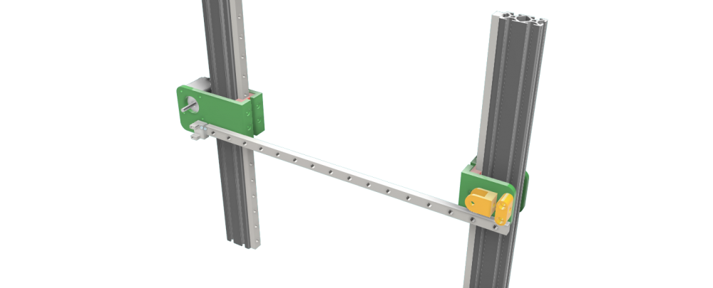
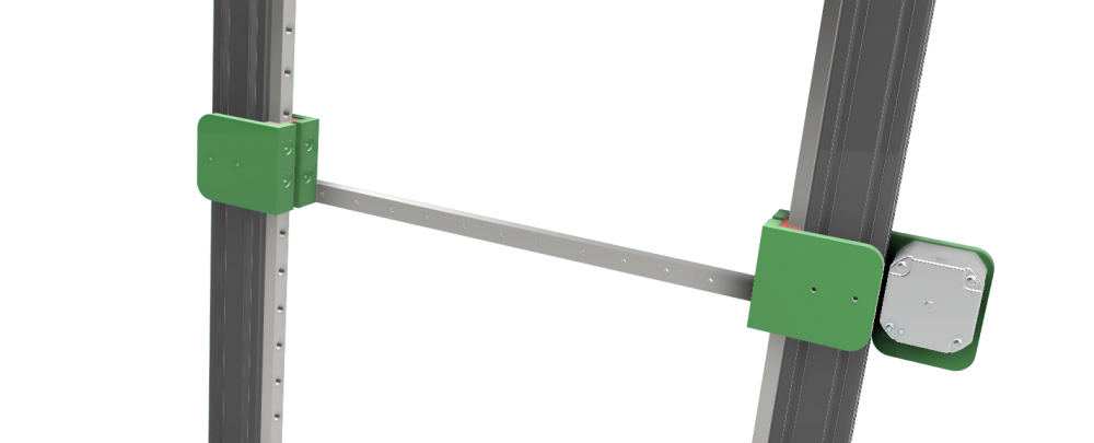 1 point
 -
Bon là c'est pas fini pour cette partie lol

 1 point
 -
1 point
-
Bonjour all, Apès plusieurs modife je me permets de partager avec vous et aussi remercier @jipee pour son taff, j'ai fini le montage me reste plus que la câblage à finir et tout sera au top. Ajout des rails linear sur l'axe Y, doublage de l'axe Z avec des pièces alu de CR-10, Bmg, skr 1.3 et tmc2208, AU TOP ! (dsl je doit poster plusieurs post car limité dans la taille à 9.77mb..)

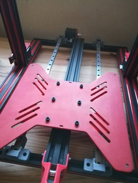
 1 point
 -
Bonjour, Faute à pas de bol et manque de rigueur câblage au remontage... Aucun de nous ne peut être épargné malgré notre sérieux si caracterisé Il faut isoler les dégâts. Soit juste l'ecran, soit juste la carte mère, ou... Les deux... Et si tu veux profiter de ton imprimante,, je ne chercherai pas midi à 14h et commanderai une nouvelle carte déjà en premier. Je dispose de la même imprimante et hormis de la fiabilisation mécanique ( galets, tendeur de courroie, guide fil, tube Capricorn extrudeur alu, etc...) je ne veux en aucun cas toucher au hardware ! Simplement parce que cette machine fonctionne très bien d'origine et qu'avec des filaments de qualité( PLA et TPU) et quelques simples réglages de bon sens affinés sous Cura, je sors d'excellentes impressions ! Quand au leveling, les molettes me vont très bien au teint ! Et avec près de 200 h d'impressions, je me contente juste de rares fois à un contrôle. En espérant t'avoir soutenu à défaut de t'avoir trouvé ta solution..., je t'épargne ma place de profil épinglé pour laisser la place à un maker bien plus calé dans le hardware Dicton du jour: "Quand ça fonctionne on ne touche à rien " C'est aussi ce que j 'applique depuis toujours, dans le monde de l'ancienne par exemple Courage, patience et à très vite pour de bonnes nouvelles !1 point
-
Bonjour je vais essayer de te répondre allor pour ce la il y a une super tools ecrit en python installer la dernier version de Python3.x pas la version python2 https://www.python.org/ https://www.python.org/ftp/python/3.8.1/python-3.8.1.exe avec pip install esptool Pour récupérer les caractéristiques de la carte, exécutez la commande esptool.py –port COMx flash_id esptool.py flash_id Pour effacer la puce flash entière (toutes les données remplacées par des octets 0xFF): esptool.py erase_flash le plus simple regarde ici esptool flasher-firmware-esptool-py-esp8266 ESP3D wiki1 point
-
La ENDER 3 PRO ou non est en 24V, le bed d'origine fait 220W: tu dois choisir un mosfet qui encaisse minimum 10A, plutôt 20A pour être tranquille avec ces chinoiseries. La sortie de la carte mère est en 24V pour le bed donc il faut s'assurer que ton mosfet encaisse cette tension pour la commande. Un fois installé la carte mère n'aura plus beaucoup d'intensité à fournir d'où le petit connecteur sur le mosfet. En général fait pour 1A max (3A pour les vrais de JST) et des fils de 22AWG (~0.3mm²). Je parle bien ici du câble de commande, pour ceux qui vont du bed au mosfet et vers l'alim il faut prévoir des grosses sections. Le 15AWG suffit, il doit pouvoir passer 14A. C'est bien le connecteur qui pose problème sur les anciennes Ender 3, c'est un problème connu et le simple fait de l'enlever ou de le remplacer par un vrai corrige ce soucis. Sur les récentes Creality a corrigé. Il n'y a rien à modifier dans le firmware et ça sollicitera moins la carte mère. Attention toute fois à la qualité du produit car ce modèle en particulier est particulièrement lowcost et il peut y avoir de mauvaises surprises.1 point
-
Sur ton exemple ça accepte entre 12 et 50V donc ça passe sur nos alimentions 12 ou 24V. Si on prend une alimentation de 350W, le courant théorique max qu'elle peut fournir est 350/12 = 29.xx A (je prends 12V pour avoir le max A possible) donc 30A max pour arrondir. Le mosfet étant donné pour imax de 30A ce qui correspond justement à la consommation théorique max de ton imprimante au complet, on peut dire qu'il suffira largement pour alimenter juste ton bed. Bah ta CM ne peut qu'apprécier mais ça fait des cables supplémentaires à bien dimensionner côté AWG et des contacts supplémentaires. Côté sécurité je ne sais pas. Y'a sûrement un ingé sécurité qui traîne sur le forum pour te répondre1 point
-
C'est pratiquement le prix d'un nouvel extrudeur non ? Edit: ah non ça fait plein de pièces de rechange. Faut voir si ce sont les bonnes dimensions Perso je suis fainéant, je remplace tout.1 point
-
Hello hello J'y connais rien mais c'est possible en effet que, si la noix en laiton ne tient qu'avec une seule vis, elle se mette de traviole et génère un blocage. @Colinette commence par ça,1 point
-
C'est que le roulement à billes est mort. A part le changer, ya pas grand-chose à faire en attendant la pièce. Peut-être le démonter, nettoyer, graisser....1 point
-
Sur ce, mon chat Shonen et moi vous disons bonne nuit (enfin lui il dit miaou mais....)
 1 point
 -
Par contre je comprendrai jamais les gens qui utilisent ces pseudo vis cruciforme qui sont merdiques au possible à visser correctement vu le peu de profondeur de l'empreinte...1 point
-
Je pense que @pafpaf n'a pas tort (et le tort tue ). Par contre le fichier joint possède une extension gcode, une fois l'extension remplacée par jpg, elle devient une image . La pièce s'est décollée pendant l'impression, le filament a continué de sortir mais comme il n'avait plus rien où se déposer, il a formé ce beau plat de spaghetti (c'est plutôt l'expression que l'on utilise). Si tu utilises Octoprint, tu peux ajouter un plugin qui détectera le plat de spaghetti en train de cuire .1 point
-
J'ai modélisé différents adaptateurs !1 point
-
J'avais prévu une grille pour l'avant mais elle est trop épaisse , ça tape contre l’écran ... Je mets le stl pour les intéressés (et/ou fan de Portal) Je crois l'avoir trouvé sur myminifactory mais pas sur ... 40mm portal fan cover.stl
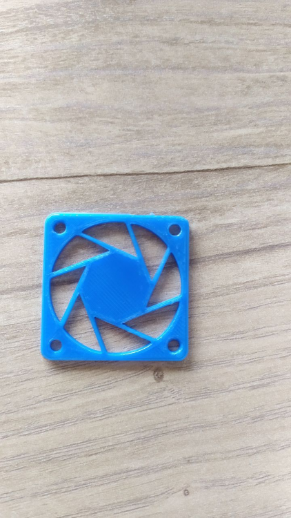 1 point
 -
Comme dans 99% des cas, le soucis est entre la chaise et l'imprimante ^^ La documentation est clair et tout est donné dedans, suffit de la suivre à la lettre ;) Et en cas de problème, un peu de courtoisie et de politesse avec le sav...1 point
-
Ah tiens ! Mr Papou3D !!!! Déja tu n'utilises pas le firmware proposé dans la doc, ça ne marchera jamais.....commence par lire et comprendre la doc. Et d'autre part quand je reçois un mail de SAV et qu'il commence par "de la merde votre touch mi impossible de l’installe dans marlin avec une ramps 1.6".... Va falloir reformuler ta demande auprés du SAV si tu veux que ce soit pris en compte !1 point
-
Ces fichiers sont généré automatiquement par dgus tool il faut supprimer les caractères « chinois » sinon l’écran ne prends pas les modif on peu les appeler 13.bin et 14.bin1 point
-
Toutafé (j'en ai deux autres que j'utiliserai en alternance suivant mon humeur / humour). Celui là c'est l'esprit «dépanneur» Pour la vitre, je ne parlais pas de coller la base magnétique dessus pour pouvoir ensuite par aimantation placer la tôle recouverte de PEI mais de coller une feuille de PEI sur la vitre (quand le plateau n'est pas franchement plan) sinon ça alourdirait de façon notable le plateau.
 1 point
 -
Salut ! Moi aussi je m'intéresse aux scanners 3D... et à tout ce qui s'y rapproche de loin et de près depuis un moment déjà. Je suis d'accord : Si on parcours le net à la recherche d'informations on peut vite s'y perdre... Tout d'abord il est impératif de préciser un détail : Chaque Scanner 3D, que cela soit un modèle "DIY" (pour développeurs/bricoleurs comme le Kinect ou le Ciclop) ou un modèle Semi-pro (comme le Matter & Form) ou un modèle plus "Professionnel" (comme le SLS DAVID SCANNER), ils ont tous leurs avantages et leurs lots d'inconvénients. Déjà, en premier lieu, il y a une question à laquelle il faut se poser la question : Qu'est-ce que je veut scanner en 3D ? Tout les scanners 3d ne se valant pas, ils ne permettent pas tous de scanner les mêmes choses. Le kinect... certes a ses avantages : Abordable, facile à utiliser, etc... mais à sont lot d'inconvénients : Ne peut scanner que les "grands objets", Distance de recul obligatoire, etc... Le Matter & Form : Dans la moyenne en terme de précision. Inconvénient : Ne peut scanner que de petits objets (guère plus grand qu'une tasse à café). Je vais te parler plus franchement, j'ai pût tester différents scanner 3D : Le Kinect Plus réservé à des bidouilleurs. J'ai acheté un caméra Kinect 360, pour 10€... j'ai ensuite acheté le kit "officiel" pour brancher en USB sur PC (pour 17,99€ à l'époque), le kit officiel n'étant plus commercialisé et fabriqué, le prix du kit s'est un peut envolé ses derniers temps, il est revendu en moyenne entre 50 et 100€ désormais. Je te conseil de te tourner vers les kits "Clone Chinois", tu en auras pour moins de 10€. L'application en version "gratuite", en cherchant bien sur le net, permet de tester la kinect. L'application en version "payante", au tarif de 129€, apporte quelques fonctionnalités indispensable en usage "pro". J'ai testé le Kinect 360 durant plusieurs jours, avec le logiciel en version "gratuite", j'ai été déçu de ne pas pouvoir scanner ce que je voulais (des figurines de 20-30cm). J'ai revendu la Kinect et le kit quelques jours plus tard. Les gros avantages : Facile d'utilisation Ne nécessite pas un PC ultra performant. Les inconvénients : On ne peut pas tout scanner. Le Matter & Form V1 ou V2 Attention ! 2 versions existent. Le capteur est plus sensible sur la version 2. Je vais être honnête : Je ne l'ai pas eût direct en main. Je n'ai pût le voir en action que sur un salon. Franchement... c'est un scanner 3D qui utilise un procédé déjà obsolète. Une caméra et 2 lasers viennent scanner l'objet posé sur un plateau rotatif. C'est très similaire à un Ciclop. Et d'ailleurs le rendu de précision final est très similaire au Ciclop. La raison ? Le Matter & Form utilise le même procédé de scanner datant de 2013. Cela fait donc 7 ans. Donc pour moi, il est déjà obsolète au vue des procédés utilisés actuellement. Pour rappel un Ciclop coûte 3 fois moins chère que le Matter & Form. Le gros avantage : Facile à transporter Le gros inconvénient : Ne permet pas de scanner un objet guère plus gros qu'une tasse à café. Si il t'intérèsse, je te recommande de guetter la bonne affaire sur leboncoin/ebay. Il y a quelques jours un Matter&Form V2, sur leboncoin était en vente à 250€. Le Sense 3D Scanner de chez 3D System C'est le scanner qui correspondrait à ton budget. Il est simple d'utilisation. Par contre, il nécessitera de respecter impérativement la Configuration Minimale requise : un Intel Core i5 (minimum 2e génération) - 4Go de RAM - Mémoire vidéo de 4Go minimum. Sans quoi... il ne fonctionnera même pas. Précis, si on prend le soin de scanner lentement (en suivant les indications du logiciel). Taille maximum des objets : 2 x 2m. C'est le Scanner 3D que j'ai pût brièvement testé et prendre en main. Je cherche à en acheter un depuis quelques jours... faute à désaccord sur le prix avec un vendeur cela n'a pas pût se faire. D'occasion sur le net, il se trouve parfois entre 150 et 300€, si il t'intéressse, guette la bonne affaire sur leboncoin. Il y en a fréquemment qui sont mis en vente. Le Ciclop En quelques mots : Scanner en kit - Pas chère (moins de 100€) - Pour bidouilleurs averti. Une fois qu'on a trouvé le truc pour le faire fonctionner, c'est un scanner 3D qui fait le taf. Mais il ne faut pas s'attendre à une grande précision. C'est pour les bidouilleurs qui veulent s'initier. Mais la qualité des objets en 3D sera à la hauteur du prix. Un scanner 3D de type SLS (Scanner par projection de lumière structurée). Je vais être direct : J'en monte un moi même. Pourquoi ?! Ce type de scanner 3D est généralement commercialisé entre 2500€ et 8000€ selon les modèles... voir plus. Mais en le fabricant a partir de rien... cela réduit les coûts. Pour l'instant, j'ai investit pour moins de 200€... en cherchant au maximum la bonne affaire. C'est le type de scanner 3D parmis les plus précis actuellement sur le marché. Ils sont fait pour un usage professionnel et semi-pro. J'ai un sujet là dessus ici : Comme tu l'auras compris... je m'en fabrique un de toute pièces... avec des pièces plus "low cost"... mais c'est un "projet" toujours en cours. Il y a quelques logiciels pour Scanner SLS qui sont gratuit et complet sur internet. Et en dernière possibilités : La Photogrammétrie Si tu connais pas, il s'agit juste d'un procédé qui utilise des photos pour les transformer en "objets 3D". De plus en plus de Scanner 3D vont soit utilisé la Photogrammétrie... soit utilisé la combinaison de la Photogrammétrie et de la Lumière Structurée... comme par exemple le Creality-CR-T. Enfin bref... va voir cet autre sujet qui traite de la Photogrammétrie : Le gros avantage de la Photogrammétrie est son prix : RIEN ! 0€ ! (sauf si tu n'as rien) Il y a des logiciels de photogrammétrie gratuit sur le net. Cela ne nécessite qu'un appareil photo numérique... ou un Smartphone. Et avec beaucoup de temps et de patience, on peut vite arriver à des résultats... assez impressionnant. Le seul inconvénient : Si tu veut scanner des objets et obtenir des modèles précis et rapidement... il te faudra investir dans du matériel informatique "orienté Gamer" pour accélérer la vitesse de traitements des images et obtenir une meilleure qualité. PS : Oh ! Un voisin Montluçonnais ! Cela fait plaisir... je me sent moins seul d'un coup !1 point
-
Salut à tous ! Je tente ma première participation à la communauté. J'ai dessiné une version d'un refroidissement pour la Hotend et support ventilateur pour le filament sur mon U30 PRO Le But étant de passer sur un ventilateur 40*40 pour la Hotend (donc théoriquement moins bruyant) et de garder plus ou moins le même style de refroidissement pour le filament. Personnellement j'imprime que du PLA pour le moment et déjà tout d'origine j'avais pas de souci du coup je laisse le projet FANG pour plus tard. Je pense que quelques photos valent mieux qu'un long discours, si certain sont intéresser je peux partager le STL ou le fichier fusion 360 pour adapter à la sauce de chacun. Bon print à tous !
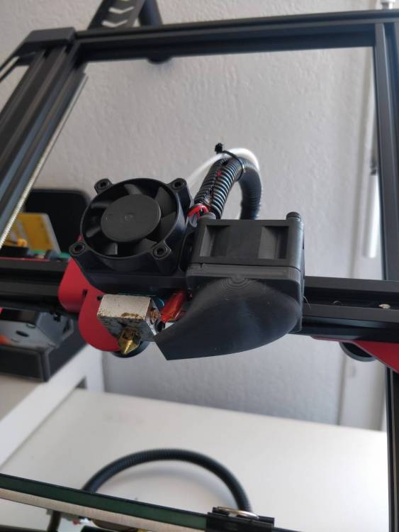

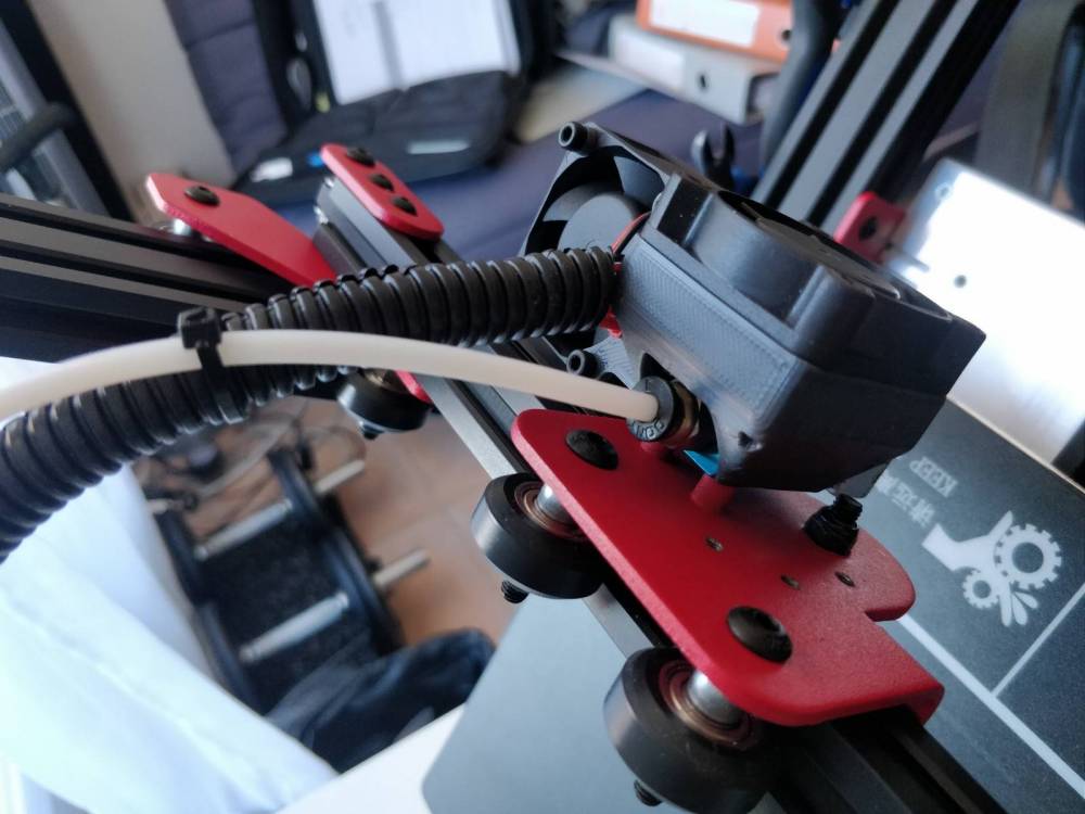
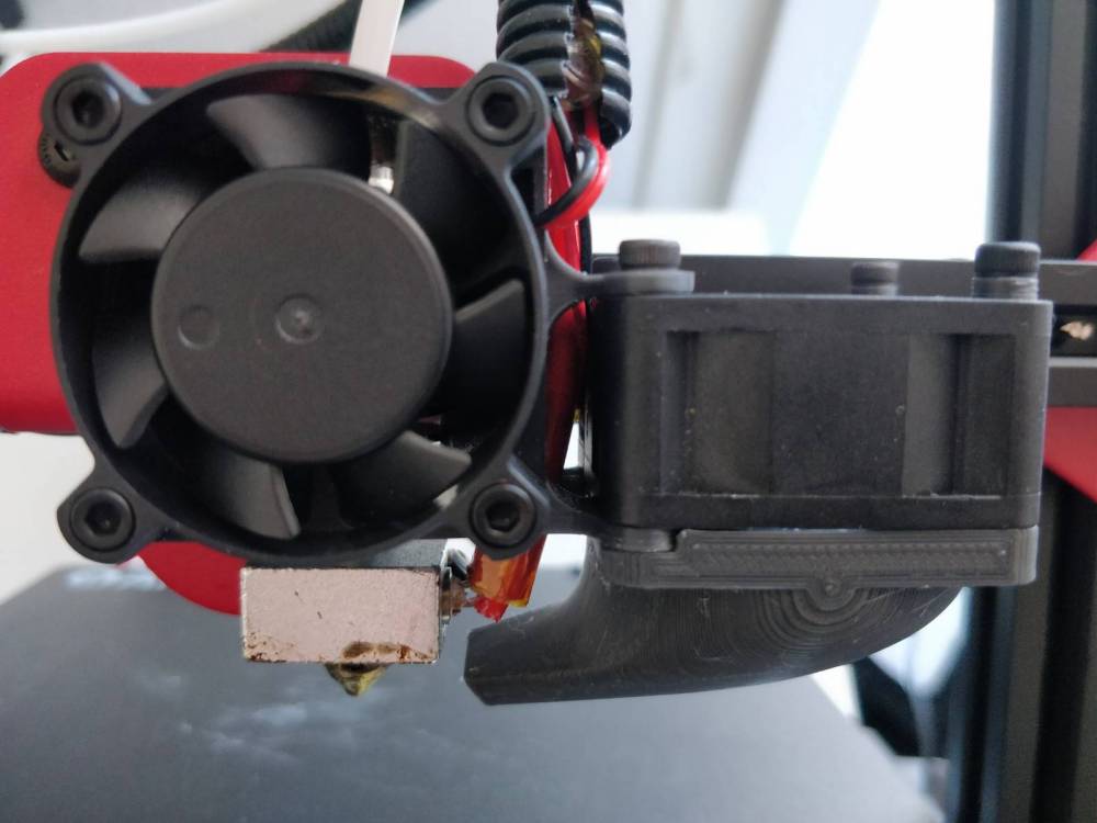
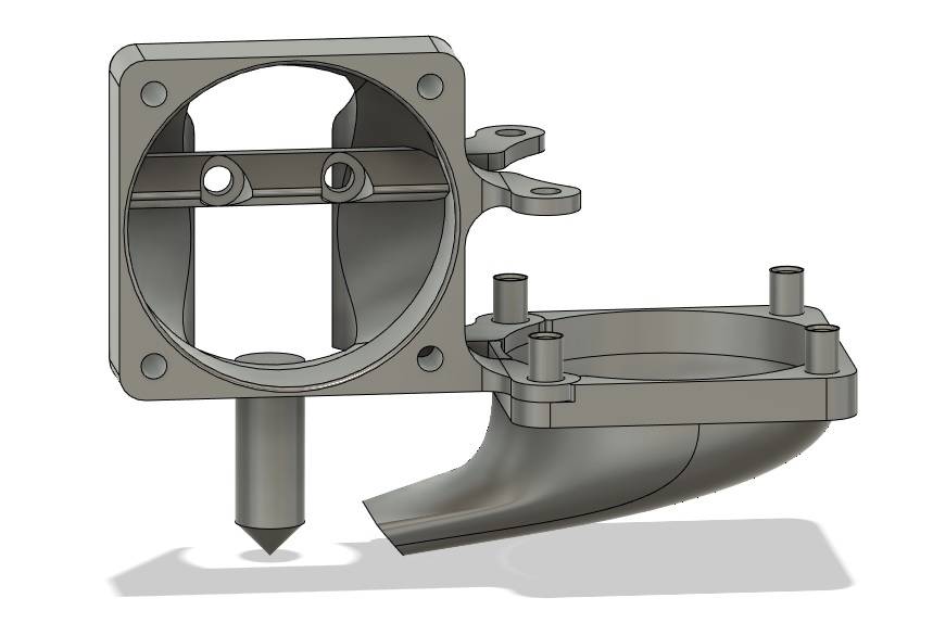 1 point
 -
Salut à tous, Mon dernier gadget, un truc pour savoir si votre congélateur a décongelé pendant vos vacances et si vous n'allez pas mourir en en mangeant le contenu. Le système est connu, je n'ai rien inventé.On met un glaçon avec une forme particulière dans le congélateur. Si à votre retour de vacances la forme ne ressemble plus à rien, c'est qu'il y aura eu une coupure et que vos aliments auront probablement décongelé puis recongelé ce qui est totalement proscrit et dangereux. Mais j'aime bien les gadgets, c'est pour ça que j'ai fait le mien dont on peut se passer à 100% Comment ça marche ? 1/ Vous remplissez le tube d'eau 2/ Vous le mettrez au congélo 3/ Une fois gelé, vous le retournez dans son bac et vous le laissez comme ça. Quand vous regardez, si le bac est vide, c'est que ça n'a pas décongelé, si le bac est plein de glace c'est que ça a décongelé à un moment. Voila, amusez-vous bien et bonnes vacances. Lien THingiverse : https://www.thingiverse.com/thing:3014488 Lien MyMiniFactory : https://www.myminifactory.com/object/3d-print-99400 (Liste de tous mes gadgets sur la première page de ce sujet)
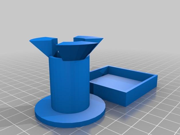
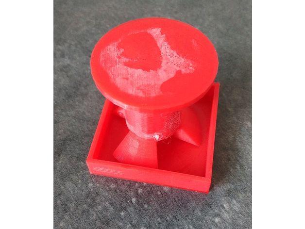 1 point
 -
bon alors voilà une vidéo, pas d'impression je fais just move axis - extrudeur et 200mm0 points


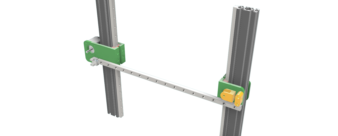
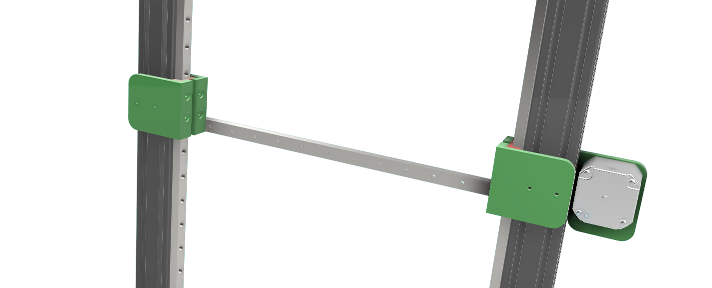
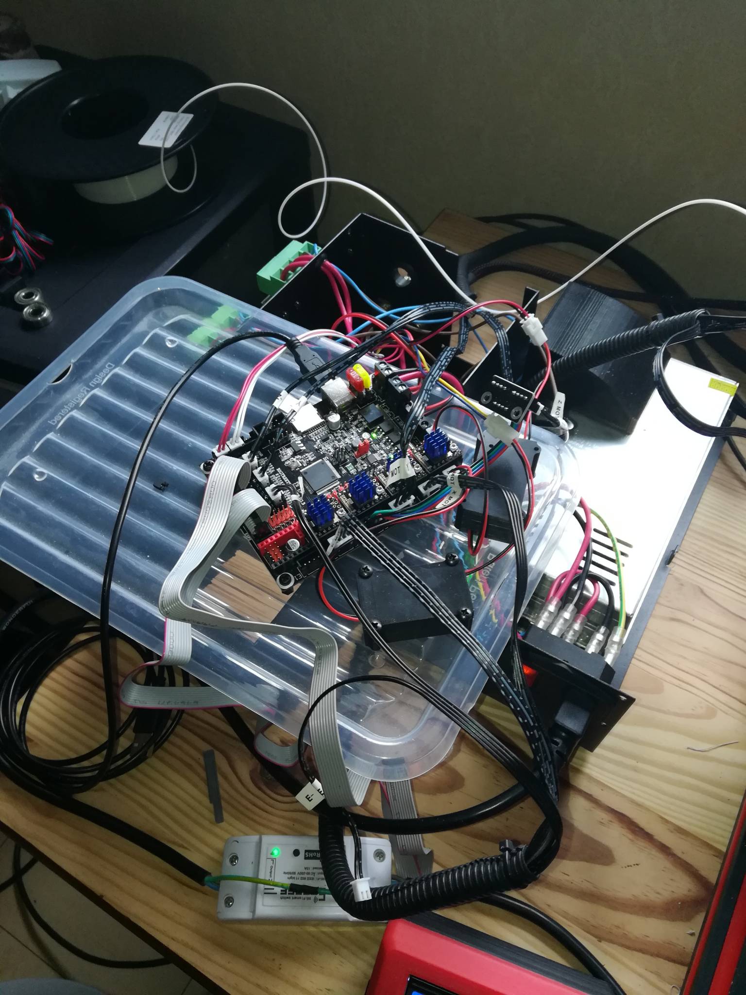
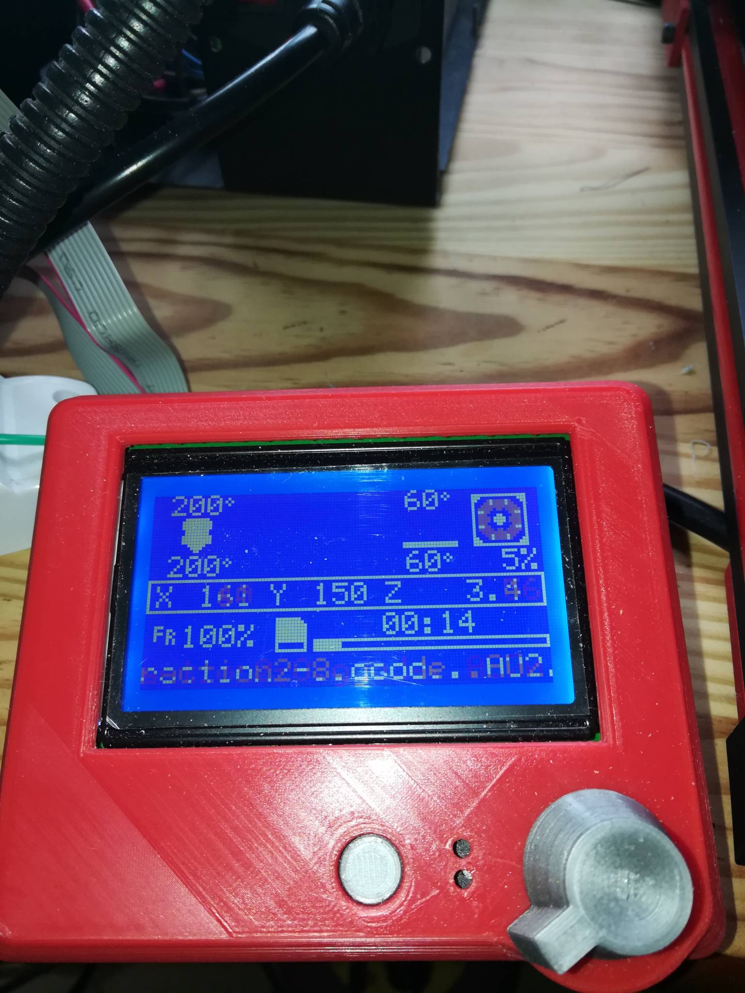
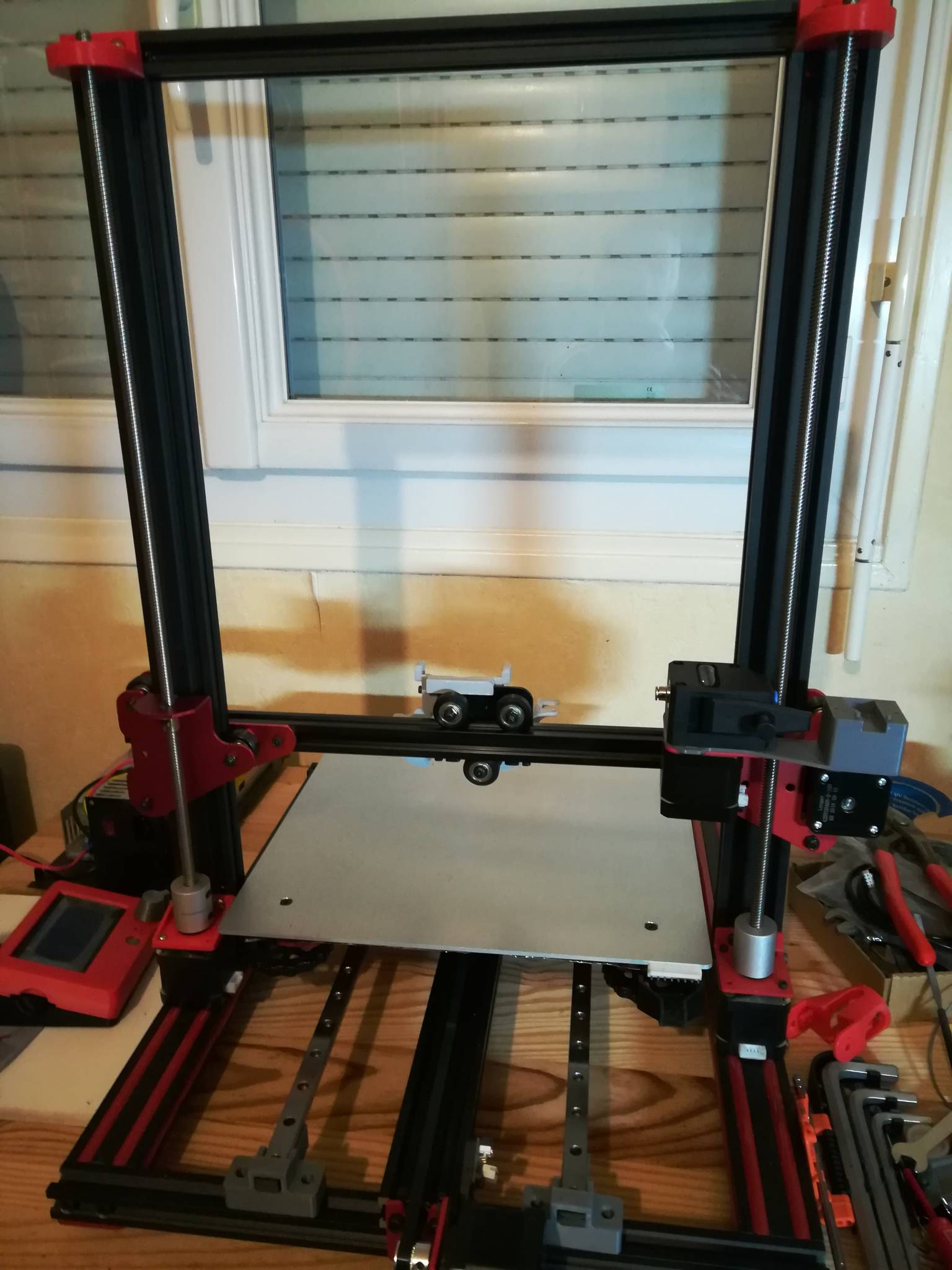
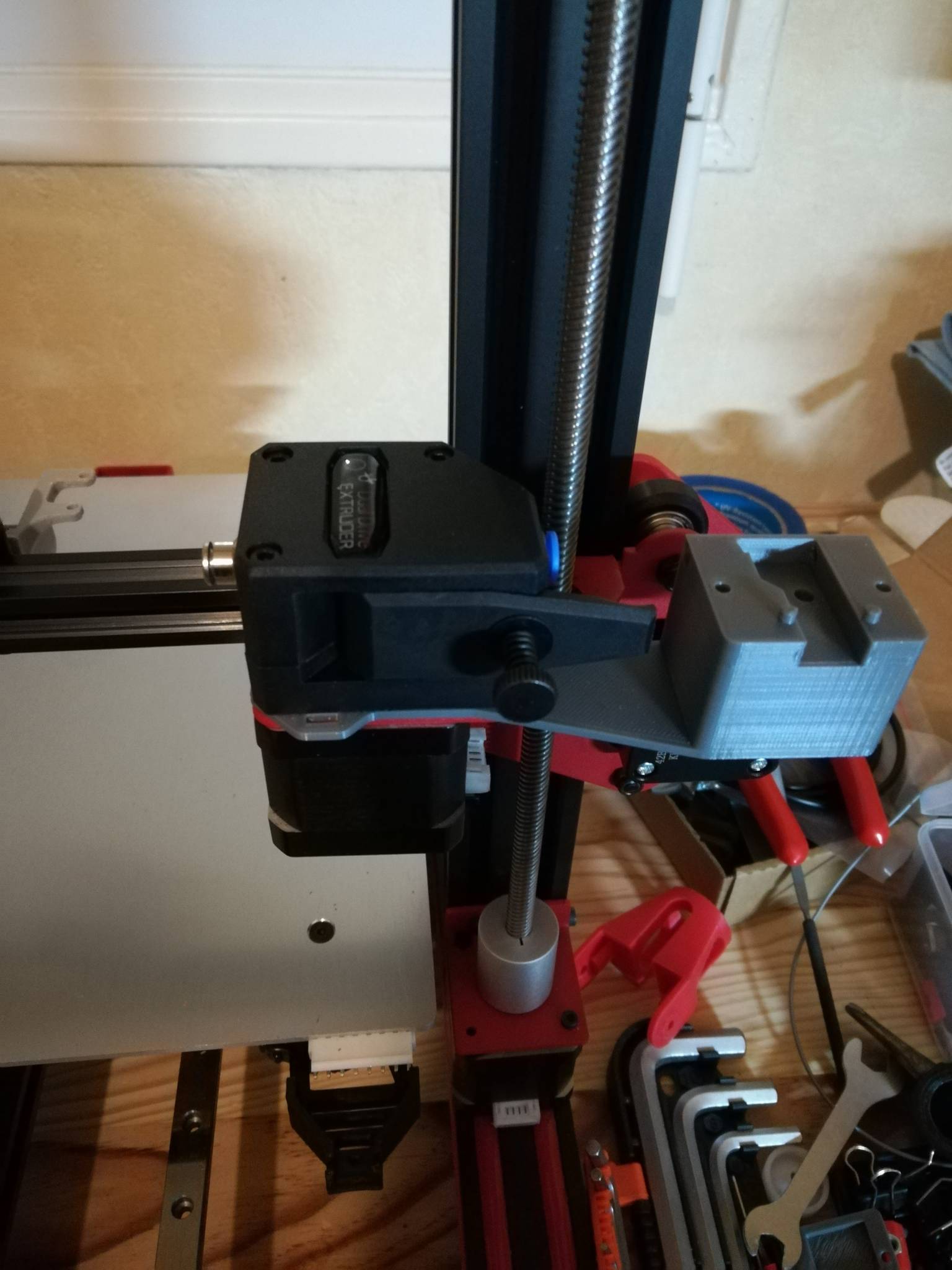
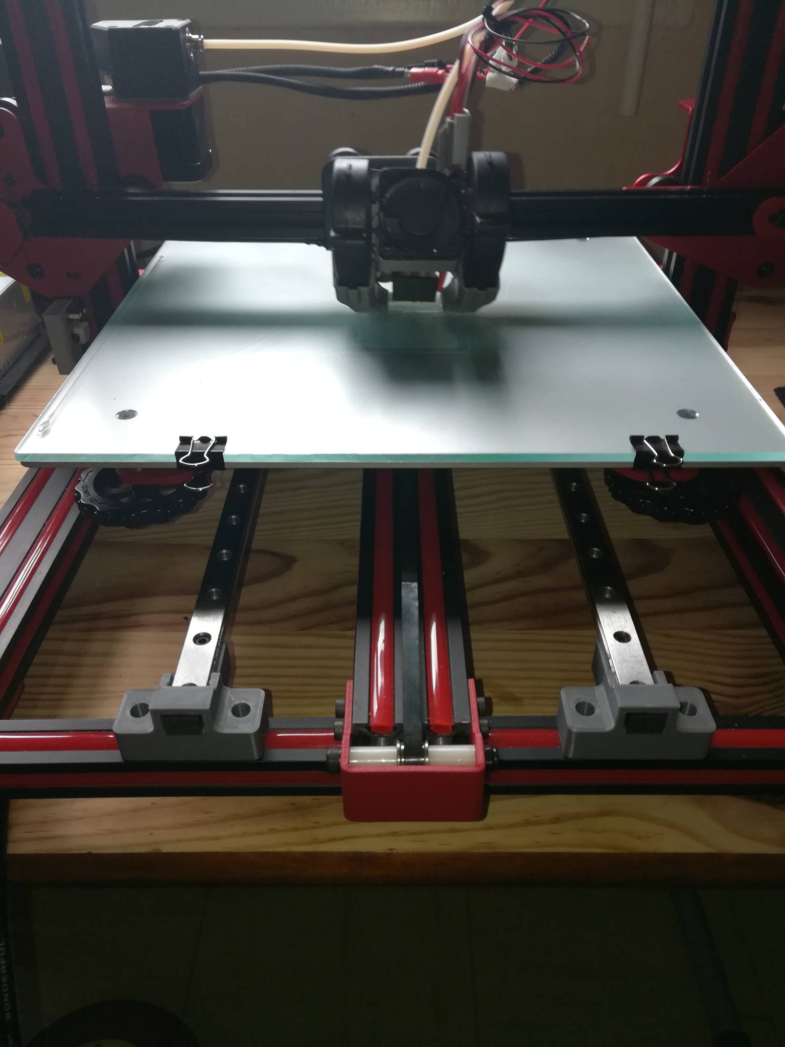
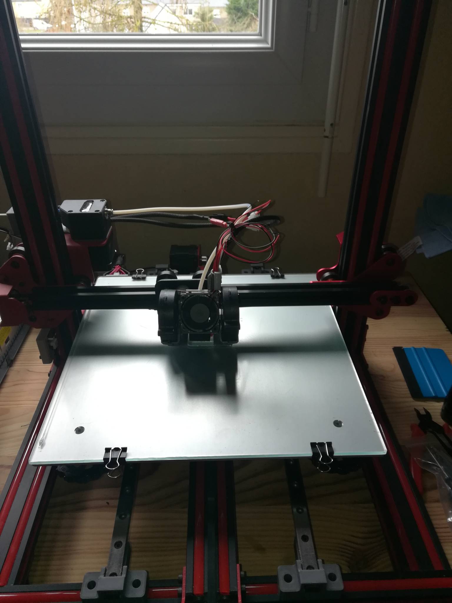
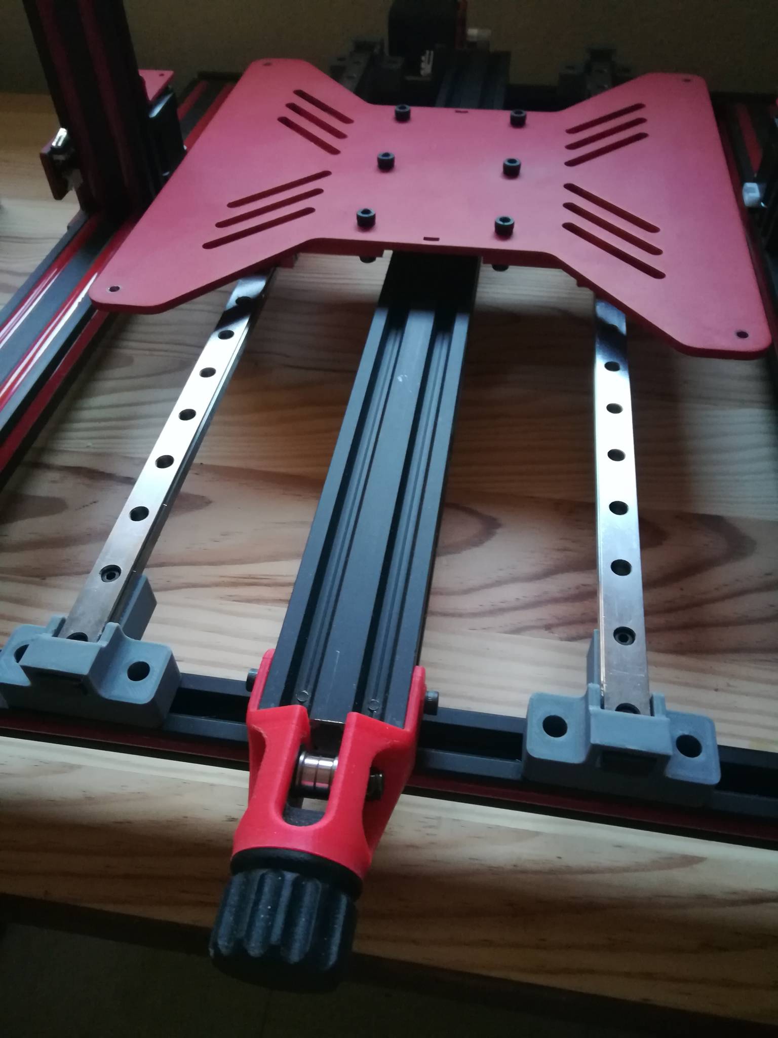

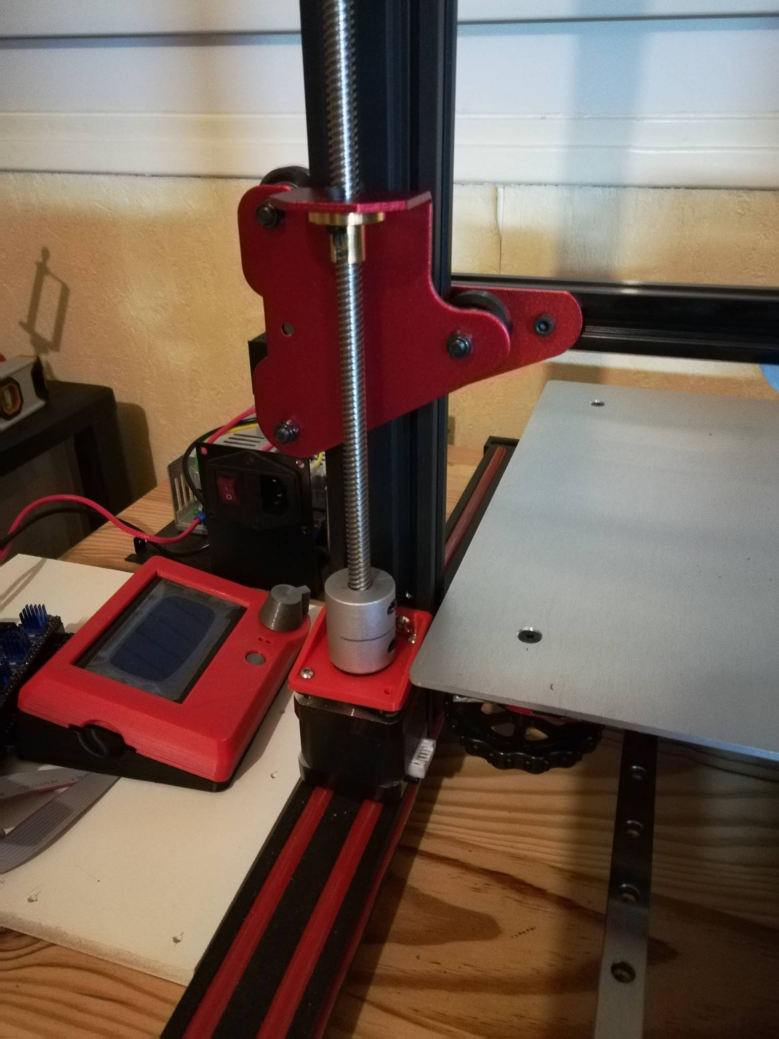


.thumb.jpeg.9a4019c4378b9b868774b9f3b684a811.jpeg)